
Steel cylinder end socket necking system

A technology of shrinking and sealing heads, which is applied to household appliances, hollow objects, other household appliances, etc., can solve the problems of unstable shape of shrinkage, roundness of products, and high rejection rate, and achieve the specification of shrinkage process and the shape of shrinkage. Consistent, high scrap rate results

Pending Publication Date: 2020-12-04
四川中腾容器制造有限公司
View PDF0 Cites 0 Cited by
  • Summary
  • Abstract
  • Description
  • Claims
  • Application Information

AI Technical Summary

Problems solved by technology

[0002] According to the requirements of national standards, there is such an important process as "shrinking" for the head of liquefied petroleum gas cylinders, and this process has been carried out for many years, and its equipment has been improved in many ways, although compared with the initial process method , the quality level of the product has been improved to a certain extent, and it can basically meet the technical requirements of steel cylinders. However, as the country has higher and higher requirements for the quality of steel cylinder production, especially the production of steel cylinders will gradually move towards the direction of fully automated process capabilities. With the development of the development, the quality requirements of each process are getting higher and higher. The main problem that still exists in this "shrinking" process is that the products after the shrinking process will have relatively large roundness errors, and the shape of the necking will also be large. Unstable, serious misalignment, high scrap rate, so that the assembly is also reflected on the bottle body at the same time, especially the uneven fit gap, which affects the quality of the ring welding of the steel cylinder and the overall appearance quality of the steel cylinder; therefore, it is proposed A cylinder head shrinking system to solve this problem

Method used


Image

  • Steel cylinder end socket necking system
  • Steel cylinder end socket necking system
  • Steel cylinder end socket necking system

Examples


Embodiment Construction

[0021] In order to make the purpose, technical solution and advantages of the present application clearer, the present application will be further described in detail below in conjunction with the accompanying drawings and specific embodiments.

[0022] In the following description, references to "one embodiment," "an embodiment," "an example," "example," etc. indicate that such described embodiment or example may include a particular feature, structure, characteristic, property, element, or limitations, but not every embodiment or example necessarily includes the specific feature, structure, characteristic, property, element or limitation. Additionally, repeated use of the phrase "according to one embodiment of the present application" does not necessarily refer to the same embodiment, although it may.

[0023] For simplicity, some technical features known to those skilled in the art are omitted from the following description.

[0024] According to one embodiment of the pres...


PUM


Abstract

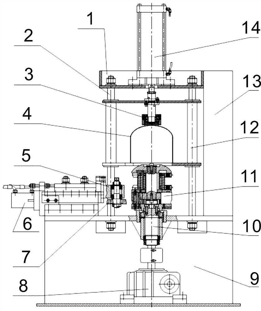
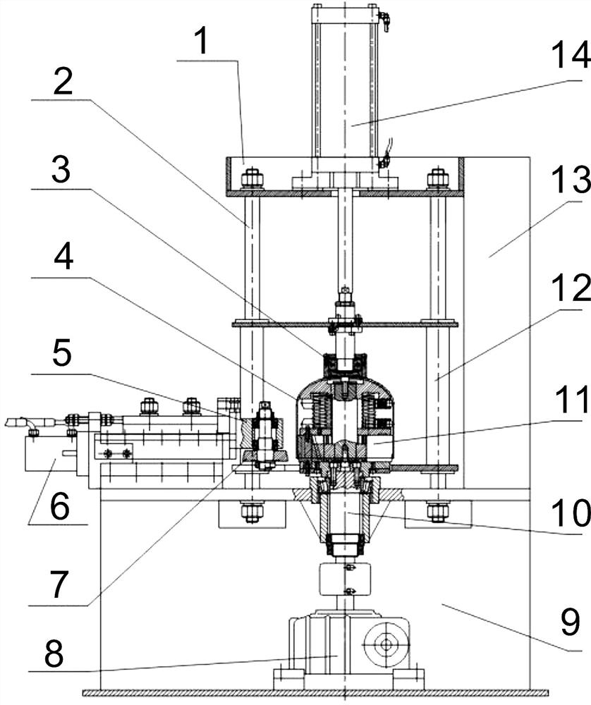
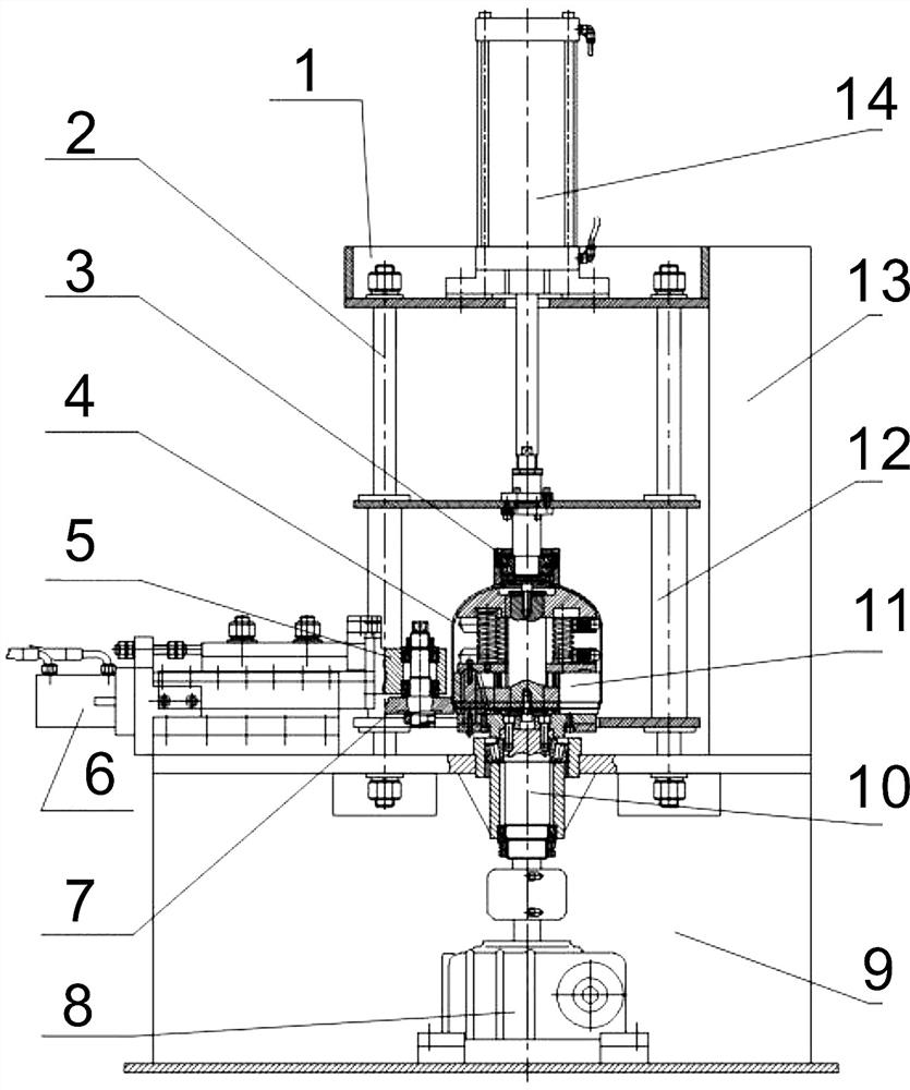
The invention provides a steel cylinder end socket necking system. The system comprises a machine frame, wherein a machine top seat is arranged at the top of the machine frame, a power head is arranged at the bottom of the machine frame, an air cylinder is arranged at the top of the machine top seat, and the output end at the bottom of the air cylinder penetrates through the machine top seat to beconnected with the top of a pressing disc; the top of the power head is connected with the bottom of a necking machine head through a main shaft; an oil cylinder is arranged in the middle of the sideend face of the machine frame, the output end of the oil cylinder is connected with an outer roller seat, and an outer roller is arranged on the outer roller seat; and the system further comprises asupporting frame used for containing an end socket. The steel cylinder end socket necking system has the advantages that the device enables the necking procedure of the end socket to be more standard,so that the necking shape is more stable; and moreover, the end socket is fixed more stably, so that the situations of dislocation and high rejection rate are avoided.

Description

technical field [0001] The invention specifically relates to a steel cylinder head shrinking system. Background technique [0002] According to the requirements of national standards, there is such an important process as "shrinking" for the head of liquefied petroleum gas cylinders, and this process has been carried out for many years, and its equipment has been improved in many ways, although compared with the initial process method , the quality level of the product has been improved to a certain extent, and it can basically meet the technical requirements of steel cylinders. However, as the country has higher and higher requirements for the quality of steel cylinder production, especially the production of steel cylinders will gradually move towards the direction of fully automated process capabilities. With the development of the development, the quality requirements of each process are getting higher and higher. The main problem that still exists in this "shrinking" pr...

Claims


Application Information

Patent Timeline
Patent Type & Authority Applications(China)
IPC IPC(8): B21D41/04B21D51/38
CPCB21D41/04B21D51/38
Inventor 李平安宋和勇
Owner 四川中腾容器制造有限公司
Learn More