Firmly buckled cable hanging bracket

A cable hanger, a solid technology, applied in the direction of cable installation, cable installation, electrical components, etc. in the tunnel, can solve the problem of the cable suspension device not being fastened tightly, so as to improve the aesthetics, easy to use, and avoid being stuck in effect

Active Publication Date: 2020-12-04
ANHUI ELECTRIC POWER TRANSMISSION & TRANSFORMATION ENG +3
View PDF17 Cites 0 Cited by
  • Summary
  • Abstract
  • Description
  • Claims
  • Application Information

AI Technical Summary

Problems solved by technology

[0003] The purpose of the present invention is to provide a cable hanger with firm fastening, so as to solve the technical problem that the fastening of the cable suspension device is not strong in the prior art

Method used


Image

  • Firmly buckled cable hanging bracket
  • Firmly buckled cable hanging bracket
  • Firmly buckled cable hanging bracket

Examples


Embodiment

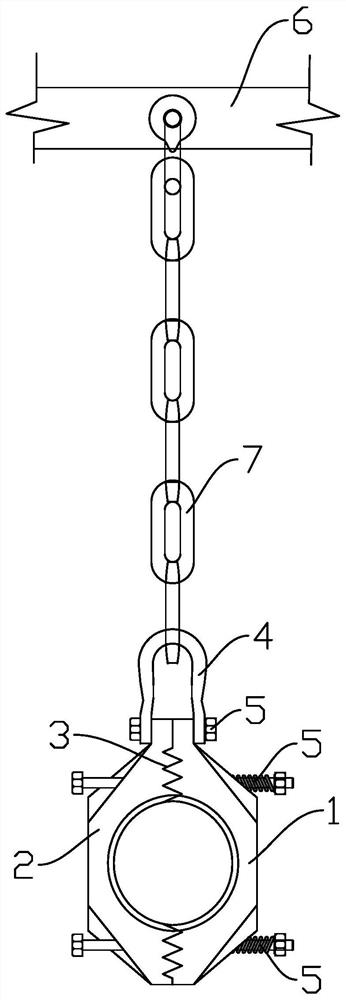
[0052] like Figure 1-2 As shown, the present invention provides a cable hanger with firm fastening. The cable hanger includes a fixed angle steel 6, a suspension device 7 and a clamp, wherein the suspension device 7 is a chain structure, and the clamp includes a connecting hardware 4 and a first claw. 1 and the second claw 2, wherein the first claw 1 is set opposite to the second claw 2, one end of the coupling hardware 4 is connected to the suspension device 7, and the other end is connected to the first claw 1 through a shaft connection or a bolt 5 connection. It is fixedly connected with the upper end of the second claw 2, and at this moment, the first claw 1 and the second claw 2 can rotate relative to each other and there is no gap between the two.

[0053] It should be noted that, as shown in the figure, the opposite parts of the first claw 1 and the second claw 2 are recessed and the joints of the two are connected by a toothed connection surface 3, so when fixing the ...

Embodiment 2

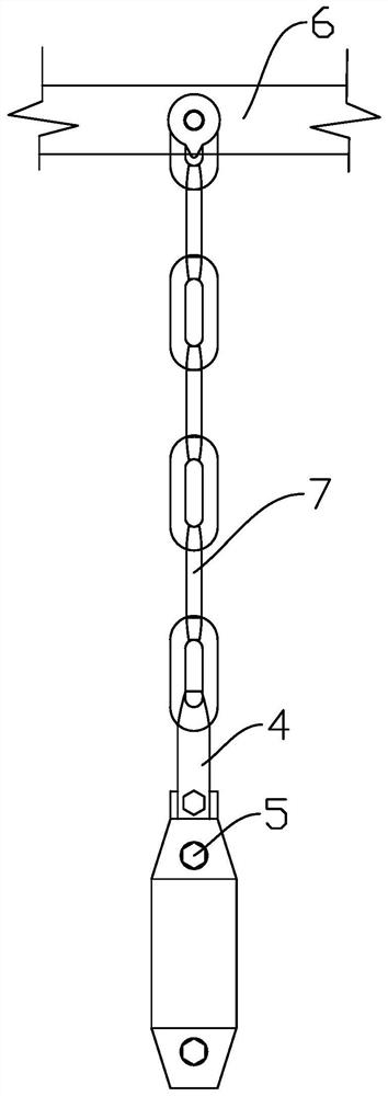
[0057] The difference between this embodiment 2 and embodiment 1 is: as Figure 3-Figure 5 As shown, the present invention provides a cable hanger with strong fastening. The clamp part of the cable hanger is quite different from the embodiment, and its overall structure is shown in the figure.

[0058] Specifically, the clamp includes a first jaw 1 and a second jaw 2, wherein the first jaw 1 includes a first connecting piece 11 and a second connecting piece 12, and the second jaw 2 includes a third connecting piece 21 and a second connecting piece 21. Four connectors 22, such as Figure 4 As shown, the first connecting piece 11 and the third connecting piece 21 are both fixedly connected with the coupling hardware 4, the second connecting piece 12 is rotationally connected with the lower end of the first connecting piece 11, the fourth connecting piece 22 is connected with the third connecting piece 21 The lower end of the rotary connection. When fixing the cables, the secon...

Embodiment 3

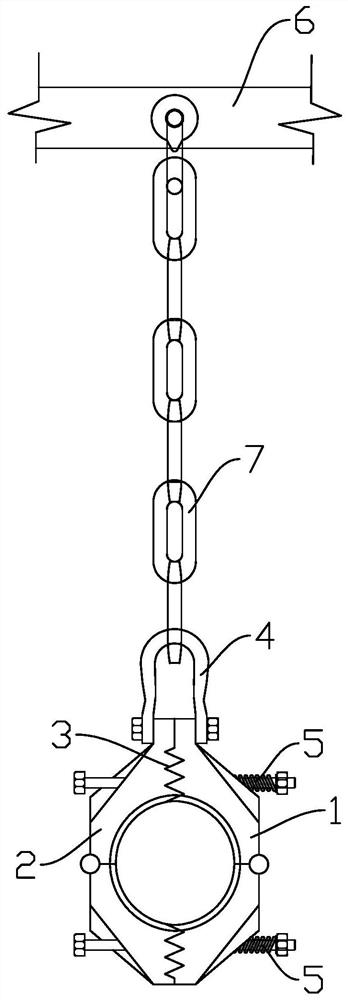
[0062] The difference between this embodiment 3 and embodiment 1 is: as Figure 6-8 As shown, the present invention provides a cable hanger with firm fastening. Compared with Embodiment 1, the cable hanger changes the fixing method of the clamp. 8 Fasten on the fixture from bottom to top by means of sleeve.

[0063] Under the action of the fixing assembly 8, the lower ends of the first claw 1 and the second claw 2 can be firmly fixed together, or the penetrating space formed by the first claw 1 and the second claw 2 can be fixed in the fixing assembly 8 The closure is achieved with the help of the , which helps to secure the cable.

[0064] Specifically, the fixing assembly 8 is a U-shaped structure with an open upper end, and its two ends extend upwards and are slightly offset toward the direction of the clamp to form buckles 81, and the distance between the two buckles 81 is smaller than the maximum width of the clamp. The maximum width of the fixed assembly 8 is greater t...


PUM


Abstract

The invention provides a firmly-buckled cable hanging bracket, relates to the technical field of cable installation, and mainly aims to solve the technical problem that a cable hanging device is not firmly buckled in the prior art. The firmly buckled cable hanging bracket comprises a clamp and a hanging device, the upper end of the hanging device is fixed, and the lower end of the hanging device is connected with the clamp. The clamp comprises a first clamping jaw and a second clamping jaw which are movably connected, a tooth-shaped connecting face is arranged at the joint of the first clamping jaw and the second clamping jaw, and when the first clamping jaw and the second clamping jaw are in a closed state, a penetrating space for a cable to penetrate through can be formed between the first clamping jaw and the second clamping jaw. The cable is fixed in the penetrating space formed by closing the first clamping jaw and the second clamping jaw, so that the cable can be conveniently hung and fixed, and meanwhile, the cable can be conveniently overhauled and expanded. A tooth-shaped connecting piece is arranged at the connecting position of the two clamping jaws, so that when the twoclamping jaws are oppositely arranged and connected in an attached mode, relative sliding between the two clamping jaws is avoided, and subsequent clamping jaw fixing operation can be conveniently conducted.

Description

technical field [0001] The invention relates to the technical field of cable installation, in particular to a cable hanger with firm fastening. Background technique [0002] With the rapid development of my country's economy, the requirements for urban beautification and power supply safety are also increasing. Therefore, cable tunnels and cable wells have also become the main channels for urban power supply. In cable tunnels and cable wells, it is generally necessary to hoist the cables to facilitate later maintenance and expansion of the pipeline, and the operation of hoisting the cables is usually achieved by using a hanger. Most of the currently used cable hangers are relatively fixedly connected by two claws. During installation, the two claws are prone to slipping and fastening are not firm, and there is a gap between the claws. This gap not only affects It is beautiful, but it will also affect the stability of the cable installation, causing the cable to be stuck and...

Claims


Application Information

Patent Timeline
Patent Type & Authority Applications(China)
IPC IPC(8): H02G3/32H02G9/08
CPCH02G3/32H02G9/08
Inventor 黄战胡益明方成高家龙王剑波刘军王和功刘大平何辉曹雾
Owner ANHUI ELECTRIC POWER TRANSMISSION & TRANSFORMATION ENG
Why Eureka
Try Eureka