A production device for rubber parts

A production device and a technology for rubber parts, applied in the field of rubber production, can solve the problems that the mixing chamber cannot be uniformly mixed, the rubber raw materials cannot be uniformly mixed, and the rubber raw materials can be prevented from flowing down smoothly. Simple process and structure

Active Publication Date: 2021-03-09
淮安聚友新能源科技有限公司
View PDF5 Cites 0 Cited by
  • Summary
  • Abstract
  • Description
  • Claims
  • Application Information

AI Technical Summary

Problems solved by technology

[0002] When producing rubber parts, it is necessary to mix the original rubber material with the ingredients first, then melt the mixed rubber material, and finally select a mold to extrude and cool it to shape. However, in actual rubber production, due to the rubber material It needs to be melted, so it is easy for the melted rubber material to solidify and stick in the passage between the mixing cavity and the plastic melting cavity, thereby preventing the smooth flow of the rubber material, and before pouring the rubber material, it needs to be Otherwise, it cannot be mixed uniformly in the mixing chamber, and if the rubber materials are poured in sequence without pre-mixing, it is even more impossible to achieve uniform mixing of the rubber materials, and the rubber materials are poured When filling, the staff needs to observe at all times, otherwise, if the raw materials are poured directly at one time, it is easy to cause the rubber raw materials to be blocked together, because the rubber raw materials also have certain plasticity, and when the rubber raw materials are opened from the packaging bag, Not loose particles, there are many particles bonded together, if not broken up in time, it will affect the molding quality

Method used


Image

  • A production device for rubber parts
  • A production device for rubber parts
  • A production device for rubber parts

Examples


Embodiment Construction

[0023] The present invention will be further explained below in conjunction with the accompanying drawings and specific embodiments, but the protection scope of the present invention will not be limited.

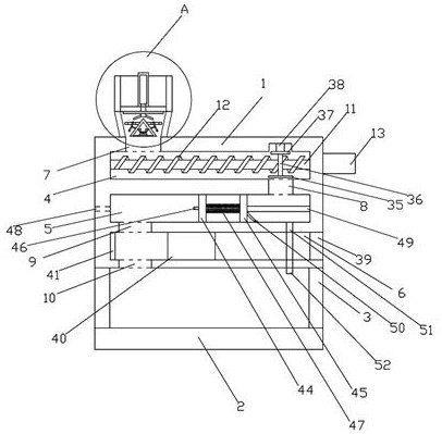
[0024] like Figure 1 to Figure 6 As shown, a production device for rubber parts includes a main box body 1 and a supporting bottom plate 2. The supporting bottom plate 2 is located below the main box body 1 and is connected to the main box body 1 through at least four legs 3. The main box body The box body 1 is provided with a mixing chamber 4, a plastic melting chamber 5 and a molding chamber 6 in order from top to bottom, and a cylindrical feeding port 7 is arranged above the mixing chamber 4, and the mixing chamber 4 and the plastic melting chamber 5 A material passage 8 is connected between them, a molding port 9 is provided between the plastic melting chamber 5 and the molding chamber 6, and a discharge port 10 vertically corresponding to the molding port 9 is provided...


PUM


Abstract

The invention discloses a novel production device of a rubber part. The novel production device comprises a main box body and a supporting bottom plate, wherein the supporting bottom plate is locatedbelow the main box body and is connected with the main box body through at least four supporting legs; the device is structurally characterized in that a material mixing cavity, a rubber melting cavity and a forming cavity are sequentially arranged in the main box body from top to bottom, a cylindrical feeding hole is formed in the upper portion of the material mixing cavity, a material passing channel is arranged between the material mixing cavity and the rubber melting cavity in a communicating mode, a forming opening is arranged between the rubber melting cavity and the forming cavity, a discharging opening which vertically corresponds to the forming opening is formed in the lower portion of the forming cavity, and a material mixing shaft is arranged in the material mixing cavity. The device has the beneficial effects that the design is reasonable, raw materials can be scattered, and pre-mixing is not needed, so that the raw materials are prevented from being blocked at the feedingopening, the working procedures are reduced, and the labor cost is reduced; and the structure is simple, the inner wall of the material passing channel can be selectively scraped and cleaned, so thatthe situation that the material passing is not smooth is avoided.

Description

technical field [0001] The invention belongs to the technical field of rubber production, and in particular relates to a production device for rubber parts. Background technique [0002] When producing rubber parts, it is necessary to mix the original rubber material with the ingredients first, then melt the mixed rubber material, and finally select a mold to extrude and cool it to shape. However, in actual rubber production, due to the rubber material It needs to be melted, so it is easy for the melted rubber material to solidify and stick in the passage between the mixing cavity and the plastic melting cavity, thereby preventing the smooth flow of the rubber material, and before pouring the rubber material, it needs to be Otherwise, it cannot be mixed uniformly in the mixing chamber, and if the rubber materials are poured in sequence without pre-mixing, it is even more impossible to achieve uniform mixing of the rubber materials, and the rubber materials are poured When f...

Claims


Application Information

Patent Timeline
Patent Type & Authority Patents(China)
IPC IPC(8): B29C43/02B29C43/34B29B7/74B29B13/02
CPCB29B7/7461B29B13/022B29C43/02B29C43/34
Inventor 詹浩
Owner 淮安聚友新能源科技有限公司
Why Eureka
Try Eureka