Coating equipment for optical fiber cable processing

A technology for cladding equipment and optical fiber cables, which is applied in the field of cladding equipment, can solve the problems of slow work progress, lack of prompt function, and inability to know the use of raw materials, etc., and achieve the effect of improving the efficiency of blanking

Pending Publication Date: 2021-11-16
深圳市三玲科技有限公司
View PDF0 Cites 0 Cited by
  • Summary
  • Abstract
  • Description
  • Claims
  • Application Information

AI Technical Summary

Problems solved by technology

[0005] In order to overcome the fact that the existing optical fiber and cable coating equipment does not have a prompt function, people cannot know the use of raw materials, and the optical fiber and cable must be manually transferred to the coating equipment, resulting in slow work progress and difficult to meet the current market The shortcoming of the demand, the technical problem of the present invention: to provide a coating equipment for optical fiber and cable processing that can automatically feed materials and has a prompt function

Method used


Image

  • Coating equipment for optical fiber cable processing
  • Coating equipment for optical fiber cable processing
  • Coating equipment for optical fiber cable processing

Examples


Embodiment 1

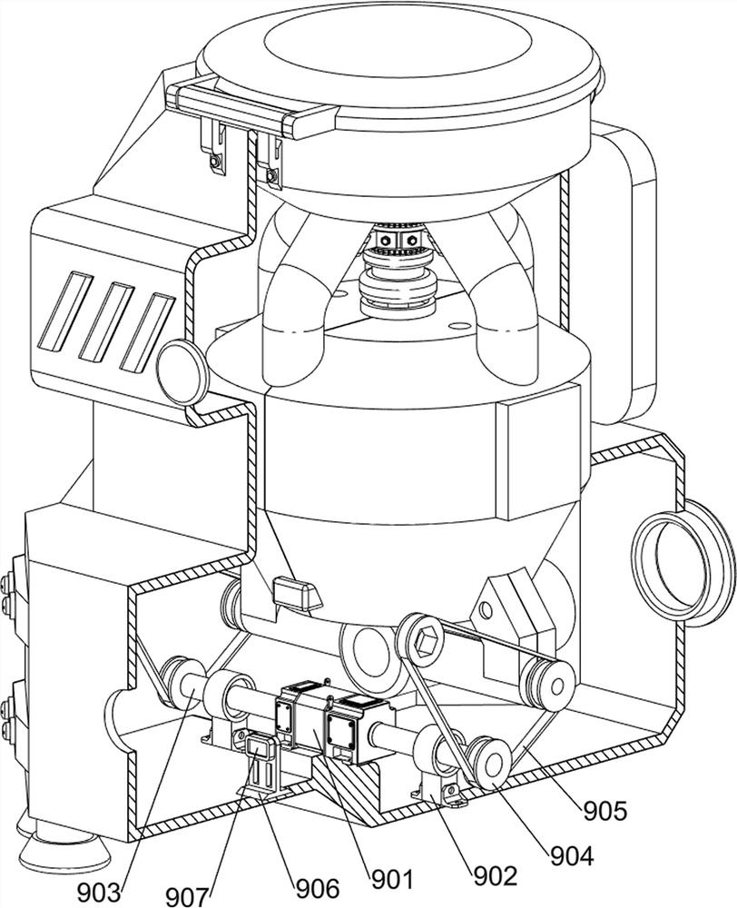
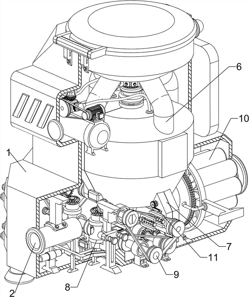
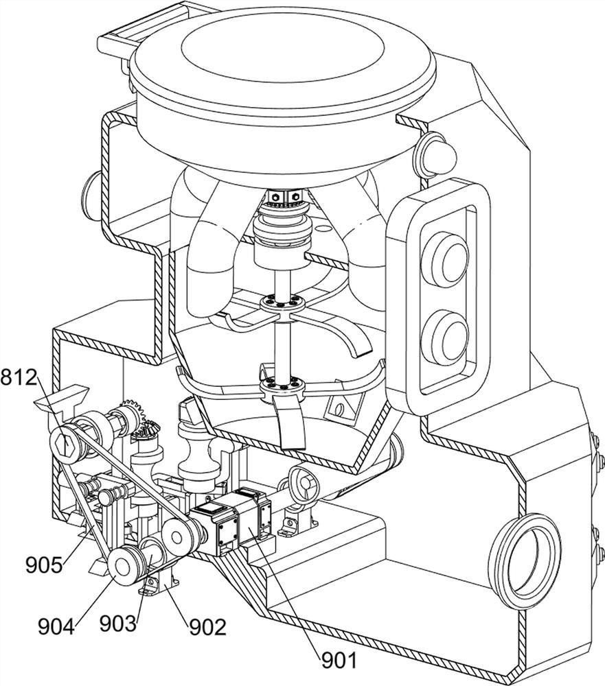
[0039] A kind of cladding equipment for optical fiber and cable processing, such as Figure 1-Figure 13 As shown, it includes a support shell 1, a feed port 2, a stirring blade 4, a discharge cylinder 5, a stirring assembly 6, an extruding assembly 7, a feeding assembly 8 and a driving assembly 9. Material port 2, a stirring assembly 6 is installed on the inner upper side of the supporting shell 1, and the stirring blade 4 is symmetrically connected up and down on the inner side of the stirring assembly 6, and an extruding assembly 7 is connected in the middle of the inner lower side of the supporting shell 1, and an outlet assembly 7 is installed on the extruding assembly 7. The feeding cylinder 5 is provided with a feeding assembly 8 on the lower left side inside the supporting shell 1 , and a driving assembly 9 is connected between the feeding assembly 8 and the extruding assembly 7 .

[0040] The stirring assembly 6 includes a cover plate 601, a feeding frame 602, a stirri...

Embodiment 2

[0046] On the basis of Example 1, such as Figure 14-Figure 19 As shown, a sizing assembly 10 is also included, and the sizing assembly 10 includes a second transmission wheel 1001, a second transmission belt 1002, a fifth support block 1003, a third rotating shaft 1004, a second bevel gear 1005, a sixth support block 1006, The first gear 1007, the second support frame 1008, the fixed plate 1009, the ring rack 1010, the second gear 1011 and the shaping roller 1012, the fifth support block 1003 is fixed symmetrically front and back in the middle of the lower side of the support shell 1, and the fifth support A third rotating shaft 1004 is rotatably arranged between the inner side of the upper part of the block 1003, and the front and rear sides of the third rotating shaft 1004 are connected with a second transmission wheel 1001, and the inner side of the second rotating shaft 903 is also connected with a second transmission wheel 1001. A second transmission belt 1002 is wound b...


PUM


Abstract

The invention relates to coating equipment, in particular to coating equipment for optical fiber cable processing. The technical problem of the invention is to provide the coating equipment for optical fiber cable processing, which can realize automatic feeding and has a prompting function. According to the technical scheme, the coating equipment for the optical fiber cable processing comprises: a supporting shell; a feeding opening which is formed in one side of the interior of the supporting shell; a stirring assembly which is arranged on the upper side of the interior of the supporting shell; stirring blades which are symmetrically arranged on the inner side of the stirring assembly; and an extrusion assembly which is arranged in the middle of the lower side of the interior of the supporting shell. When the first push rod moves rightwards, a sliding frame and a feeding wheel are driven to move inwards, the feeding wheel presses the optical fiber cable inwards, when the feeding wheel rotates, the optical fiber cable is conveyed rightwards to the discharging cylinder, the operation is repeated, and the automatic feeding effect is achieved.

Description

technical field [0001] The invention relates to a coating device, in particular to a coating device for optical fiber and cable processing. Background technique [0002] A fiber optic cable is a communication cable consisting of two or more glass or plastic optical fiber cores within a protective cladding. [0003] In the fiber optic cable industry, it is usually necessary to coat the outside of the fiber optic cable with a layer of protective skin before it can be packaged and sold later. Nowadays, in the existing fiber optic cable coating equipment, there is no prompt function after the raw materials are loaded. People cannot know the use of raw materials, which may easily cause some positions on the optical fiber cable to be uncoated, and when coating the optical fiber cable, it is necessary to manually transfer the optical fiber cable to the coating equipment, resulting in slow work progress. Difficult to meet the needs of the current market and other problems exist. ...

Claims


Application Information

Patent Timeline
Patent Type & Authority Applications(China)
IPC IPC(8): G02B6/44B65D88/68B65D90/48B65D88/54
CPCG02B6/4486B65D88/68B65D90/48B65D88/548
Inventor 陈苏华
Owner 深圳市三玲科技有限公司
Why Eureka
Try Eureka