Minimum voltage type active clamp DC-DC converter

A DC converter and voltage-type technology, applied in the direction of converting DC power input to DC power output, adjusting electrical variables, instruments, etc., can solve problems such as high related losses, large voltage stress, and increased voltage stress of the main switch and auxiliary switch

Inactive Publication Date: 2003-09-03
ZHEJIANG UNIV
View PDF0 Cites 1 Cited by
  • Summary
  • Abstract
  • Description
  • Claims
  • Application Information

AI Technical Summary

Problems solved by technology

The disadvantage of the DC-DC converter composed of this basic conversion circuit is that the converter works as a hard switch. In the continuous current mode, the related loss caused by the reverse recovery of the diode in the converter is very high. high current stress
Some converters adopt zero-voltage switching technology, which suppresses the reverse recovery current of the diode and realizes the zero-voltage switching operation of the main switch without increasing the voltage stress of the device. However, the auxiliary switching devices in the converter often do not work In the soft switching state; although the usual active clamp technology can realize the soft switching operation of the main switch and the auxiliary switch at the same time, the voltage stress of the main switch and the auxiliary switch increases a lot, and the voltage stress increases with the control duty cycle and load In addition, after the diode in the converter is turned off, the parasitic capacitance at both ends of the converter and the auxiliary inductance resonate to produce a serious voltage oscillation, and the voltage stress is large

Method used


Image

  • Minimum voltage type active clamp DC-DC converter
  • Minimum voltage type active clamp DC-DC converter
  • Minimum voltage type active clamp DC-DC converter

Examples


Embodiment Construction

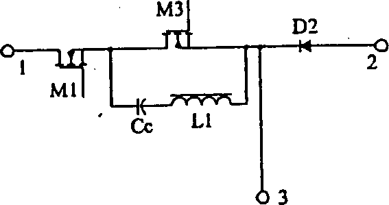
[0025] image 3 The basic conversion circuit shown includes main switching tube M1, diode D2, auxiliary switching tube M3, clamping capacitor Cc and auxiliary inductance L1, one end of the series circuit of clamping capacitor Cc and auxiliary inductor L1 connected in parallel with auxiliary switching tube M3 It is connected to the main switching tube M1, and the other end is connected to the diode D2. The other end 1 of the main switching tube M1, the other end 2 of the diode D2, and the junction 3 of the auxiliary switching tube M3 and the diode D2 are respectively the basic conversion circuit in the converter. Connecting end, wherein connecting end 3 can also be as Figure 4 Shown is the junction of the clamping capacitor Cc and the auxiliary inductor L1.

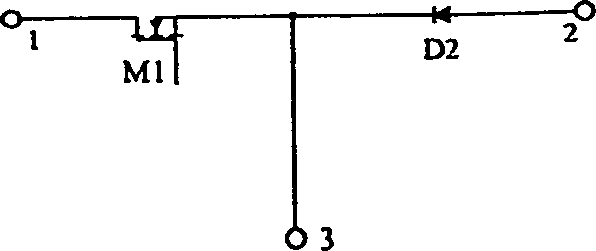
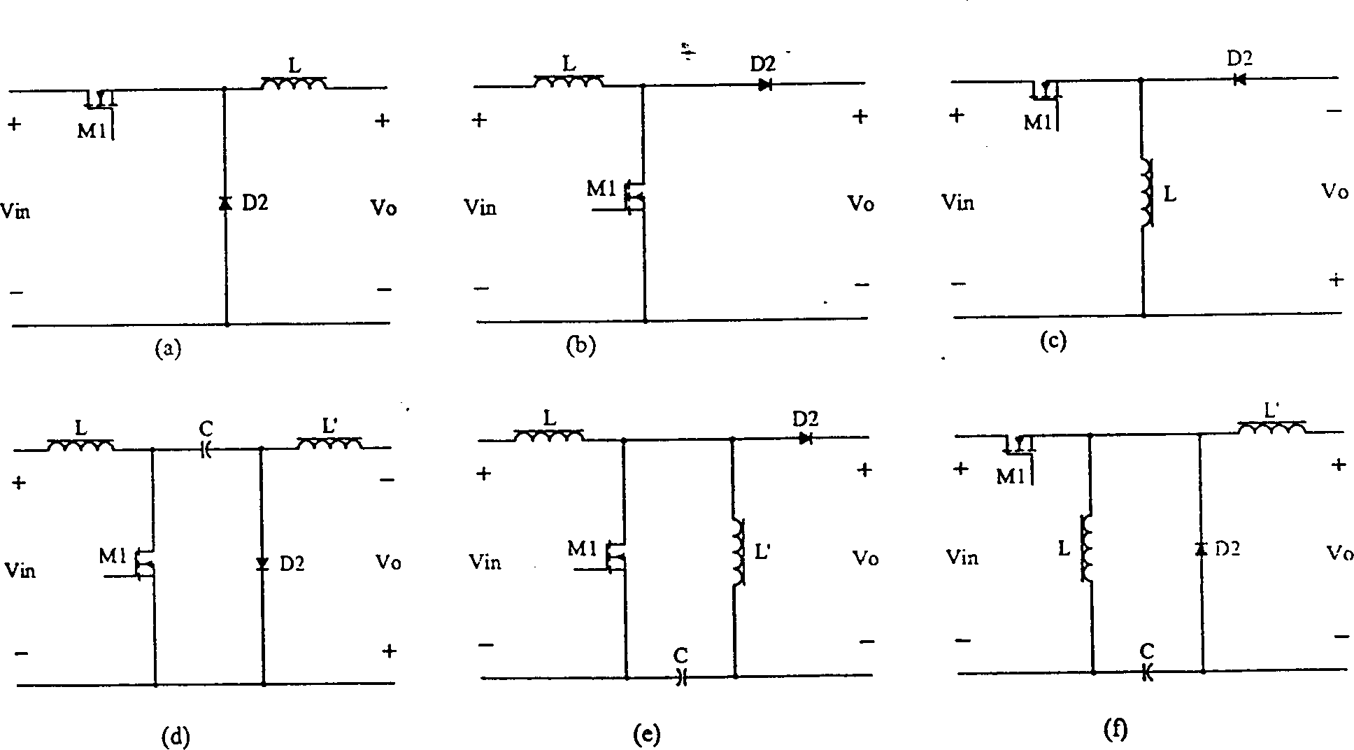
[0026] Will figure 2 Among the 6 conventional DC-DC converters such as figure 1 The basic conversion circuit shown is replaced by the connection relationship of the corresponding connection terminals as image 3 The ...


PUM


Abstract

The invention discloses a least-voltage type active clamping DC-DC converter. Circuit of the converter is formed as follows: Clamping capacitance cascaded to assistant inductance then is connected to assistant switch tube in parallel. The one end of above formed circuit is connected to a main switch tube and another end is connected to a diode, forming an invented basic converting circuit that replaces buck, boost, buckboost, Cuk, SEPIC and Zeta 6 kinds of basic converting circuit used in conventional converter. The invention has advantages of simple structure, low cost, and high working efficiency. Reverse recovery current of the diode is effectively restrained. Both of main and assistant switches of converter are zero voltage workable switches.

Description

technical field [0001] The present invention relates to DC-DC converters. Background technique [0002] figure 1 The circuit shown is connected by a switch tube M1 and a rectifier diode D2, and has three connection terminals labeled 1, 2, and 3 that are drawn out at the contact points. figure 2 The step-down converter (buck), boost converter (boost), step-up-step-down converter (buckboost) shown in a), b), c), d), e), and f) in Converter (Cuk), Sepic converter (SEPIC), Zeta converter (Zeta) and other basic conversion circuits in six conventional DC-DC converters, figure 2 Vin in each figure is the input voltage port of the converter, Vo is the output voltage port of the converter, L and L' are the inductors in the converter, and C is the capacitor in the converter. The disadvantage of the DC-DC converter composed of this basic conversion circuit is that the converter works as a hard switch. In the current continuous mode, the related loss cause...

Claims


Application Information

Patent Timeline
Patent Type & Authority Patents(China)
IPC IPC(8): H02M3/335
Inventor 陈刚徐德鸿冯波汪槱生
Owner ZHEJIANG UNIV
Why Eureka
Try Eureka