Case cooling device

A heat dissipation device and chassis technology, which is applied in the direction of dryers, drying gas arrangement, lighting and heating equipment, etc., can solve the problems of insufficient applicability of collection devices, and achieve the effect of avoiding high humidity and facilitating inflation

Inactive Publication Date: 2020-12-11
宁征兵
View PDF0 Cites 4 Cited by
  • Summary
  • Abstract
  • Description
  • Claims
  • Application Information

AI Technical Summary

Problems solved by technology

[0003] The heat dissipation device of the box body of the existing electrical cabinet cannot collect and recycle the heat generated by heat dissipation, which makes the existing collection device insufficient in applicability

Method used


Image

  • Case cooling device
  • Case cooling device
  • Case cooling device

Examples


Embodiment 1

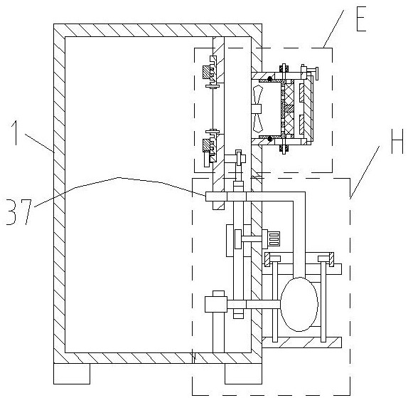
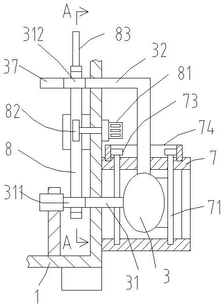
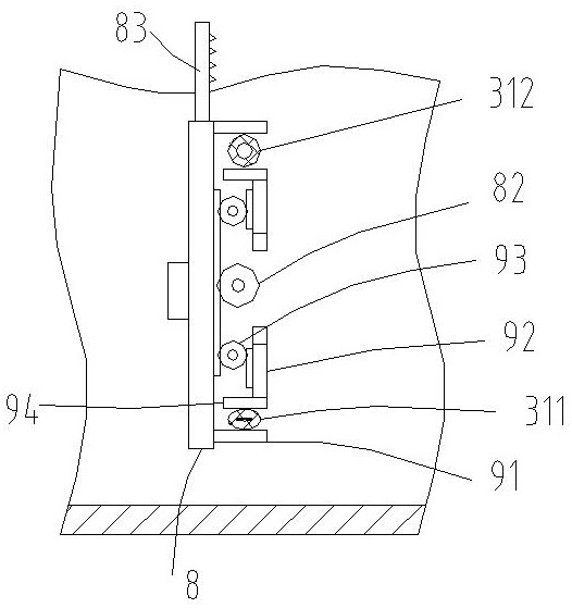
[0024] Such as Figure 1-7 As shown, a cooling device for a chassis provided by the present invention includes a box body 1, one side of the box body 1 is fixedly connected to an air intake pipe 2, the box body 1 is a sealed type except for the air intake pipe 2, and the air intake pipe 2 communicates with the box body 1 The inner cavity of the air intake pipe 2 is equipped with an air intake fan 11 near the end of the box body 1, and the air intake pipe 2 is provided with a hygroscopic sponge 53, and the outer side of the box body 1 is provided with an air bag 3, and the air bag 3 is fixedly connected with an air intake branch pipe 31, The air intake branch pipe 31 extends into the inside of the box body 1, the air bag 3 is fixedly connected to the air outlet branch pipe 32, the outside of the box body 1 is fixedly connected to the U-shaped frame 7, the air bag 3 is fixedly connected to the inside of the U-shaped frame 7, and the U-shaped frame 7, with the airbag 3 as the cen...

Embodiment 2

[0029] Such as Figure 6-11 As shown, on the basis of Embodiment 1, the end of the intake pipe 2 away from the box body 1 is equipped with a cover plate 4, and three air inlet holes 41 are arranged in an array on the cover plate 4, and the filter element 5 is slidably connected to the intake pipe 2; The filter element 5 includes a disk 51, and the disk 51 is provided with three fan-shaped grooves 52 in an array near the side of the cover plate 4. The moisture-absorbing sponge 53 is arranged corresponding to the fan-shaped grooves 52 and is fixedly connected in the fan-shaped grooves 52. Sponge 53 is arranged correspondingly, and when filter core 5 is positioned at one end close to air intake fan 11, air inlet hole 41 is coaxial with hygroscopic sponge 53, and the groove bottom of fan-shaped groove 52 is provided with ventilation hole 54, and is provided with drainage hole on disc 51 55, the drain hole 55 is connected to the moisture-absorbing sponge 53, and the axis of the dra...


PUM


Abstract

The invention discloses a case cooling device which comprises a case body, an air inlet pipe is fixedly connected to one side of the case body, moisture absorption sponge is arranged in the air inletpipe, an air bag is arranged on the outer side of the case body, an air inlet branch pipe is fixedly connected to the air bag and extends into the case body, an air outlet branch pipe is fixedly connected to the air bag, and a U-shaped frame is fixedly connected to the outer side of the case body. The air bag is fixedly connected into the U-shaped frame, a plurality of rotating rods are rotationally connected into the U-shaped frame in an annular array with the air bag as the center, each rotating rod is fixedly connected with a pressing piece, the inner arc face of each pressing piece is fixedly connected with the outer side face of the air bag, and the upper end of each rotating rod penetrates through the U-shaped frame and is fixedly connected with a linkage gear at the end. The upper side of the U-shaped frame is rotationally connected with an inner gear ring, and each linkage gear is meshed with the inner gear ring. The air bag is stretched outwards from the multiple connecting points through the multiple pressing pieces, so that air inflation of the air bag is facilitated, and the air bag is extruded to exhaust air when needed.

Description

technical field [0001] The invention relates to the technical field of chassis heat dissipation, in particular to a heat dissipation device for a chassis. Background technique [0002] The electrical cabinet is a cabinet made of steel to protect the normal operation of circuit components. The materials for making electrical cabinets are generally divided into two types: hot-rolled steel and cold-rolled steel. Electrical cabinets are widely used mainly in chemical industry, environmental protection industry, power system, metallurgical system, industry, nuclear power industry, fire safety monitoring, transportation industry and so on. [0003] The heat dissipation device of the box body of the existing electric cabinet cannot collect and recycle the hot gas generated by heat dissipation, which makes the applicability of the existing collection device insufficient. Contents of the invention [0004] The purpose of the present invention is to solve the shortcomings in the p...

Claims


Application Information

Patent Timeline
Patent Type & Authority Applications(China)
IPC IPC(8): G06F1/18G06F1/20F26B21/00
CPCF26B21/001G06F1/181G06F1/20
Inventor 不公告发明人
Owner 宁征兵
Why Eureka
Try Eureka