Tire pressure detector

a tire pressure detector and detector technology, applied in the direction of tire measurement, vehicle components, transportation and packaging, etc., can solve the problems of low tire pressure, affecting driving safety, and relying on equipment and personnel of vehicle repair shops, so as to reduce the theft rate of tire pressure detectors, accurate tire pressure data, and effective prevention from theft

Inactive Publication Date: 2010-08-17
SUNG JUNG MINUTE IND
View PDF4 Cites 20 Cited by
  • Summary
  • Abstract
  • Description
  • Claims
  • Application Information

AI Technical Summary

Benefits of technology

[0005]The primary objectives of the present invention are to improve the poor airtightness of the conventional tire pressure detectors, keep the airtightness of the tire pressure detector during replacing batteries, guarantee detection accuracy, and prevent from the air leakage caused by using the tire pressure detector.
[0007]In one embodiment of the present invention, the air-intake member has an air-intake force-action member where an air-intake locking instrument applies force. The air-intake locking instrument has a first positioning member matching the air-intake force-action member. The air-intake device also has a theft-proof element. The theft-proof element has at least one theft-proof force-action member where a theft-proof locking instrument applies force. The theft-proof locking instrument has a second positioning member matching the theft-proof force-action member. Thus, the present invention can effectively prevent from theft.
[0008]In another embodiment, the present invention further comprises a dedicated air tap protruding from a tire. The tire pressure detector is installed on the dedicated air tap via the air-intake member of the air-intake seat. The dedicated air tap includes an air tube and an air-intake tip which are formed in an integral manner. The air-intake tip is connected to a tire, and the air tube protrudes from the tire. Thus, the user needn't dismount the tire pressure detector from the dedicated air tap before tire inflation. Besides, the dedicated air tap is arranged on the lower side of the chassis. Such an arrangement will not affect the appearance of the wheel but can effectively reduce the theft rate of the tire pressure detector.
[0009]In comparison with the conventional technology, the present invention detects the tire pressure in a fully airtight air chamber. Therefore, the present invention can obtain accurate tire pressure data. In the present invention, the battery can be directly replaced without affecting detection accuracy. In the present invention, the user can conveniently inflate the tire without dismounting the tire pressure detector from the dedicated air tap. Further, the present invention has a theft-proof function. Furthermore, the present invention can keep the original appearance of the wheel.

Problems solved by technology

Too high a tire pressure or too low a tire pressure affects driving safety.
However, the driver cannot learn the tire pressure from the appearance thereof but can only rely on the equipment and personnel of a vehicle repair shop.
Needless to say, the driver cannot monitor the tire pressure in a running vehicle.
However, the prior-art patent does not have an air chamber but uses a valve core needle to press against the valve core of the air tap to control the air flowing from the tire to the tire pressure detection device.
Such a means may result in air leakage.
However, such an approach has only a limited effect on preventing from the air leakage in the engagement region of the cap and the casing.
Thus, the driver may receive wrong information, and driving safety may be affected.
However, the cap is embedded in the casing and unlikely to be dismantled from the casing.
Thus, the exhausted batteries cannot be replaced.
For consumers, such a limited service life means a poor economic efficiency.
In the prior-art tire pressure detection device, airtightness is inferior, batteries are hard to replace, economic efficiency is low, detection results are apt to be inaccurate, and air leakage is likely to occur after a long time use.

Method used


Image

  • Tire pressure detector
  • Tire pressure detector
  • Tire pressure detector

Examples


first embodiment

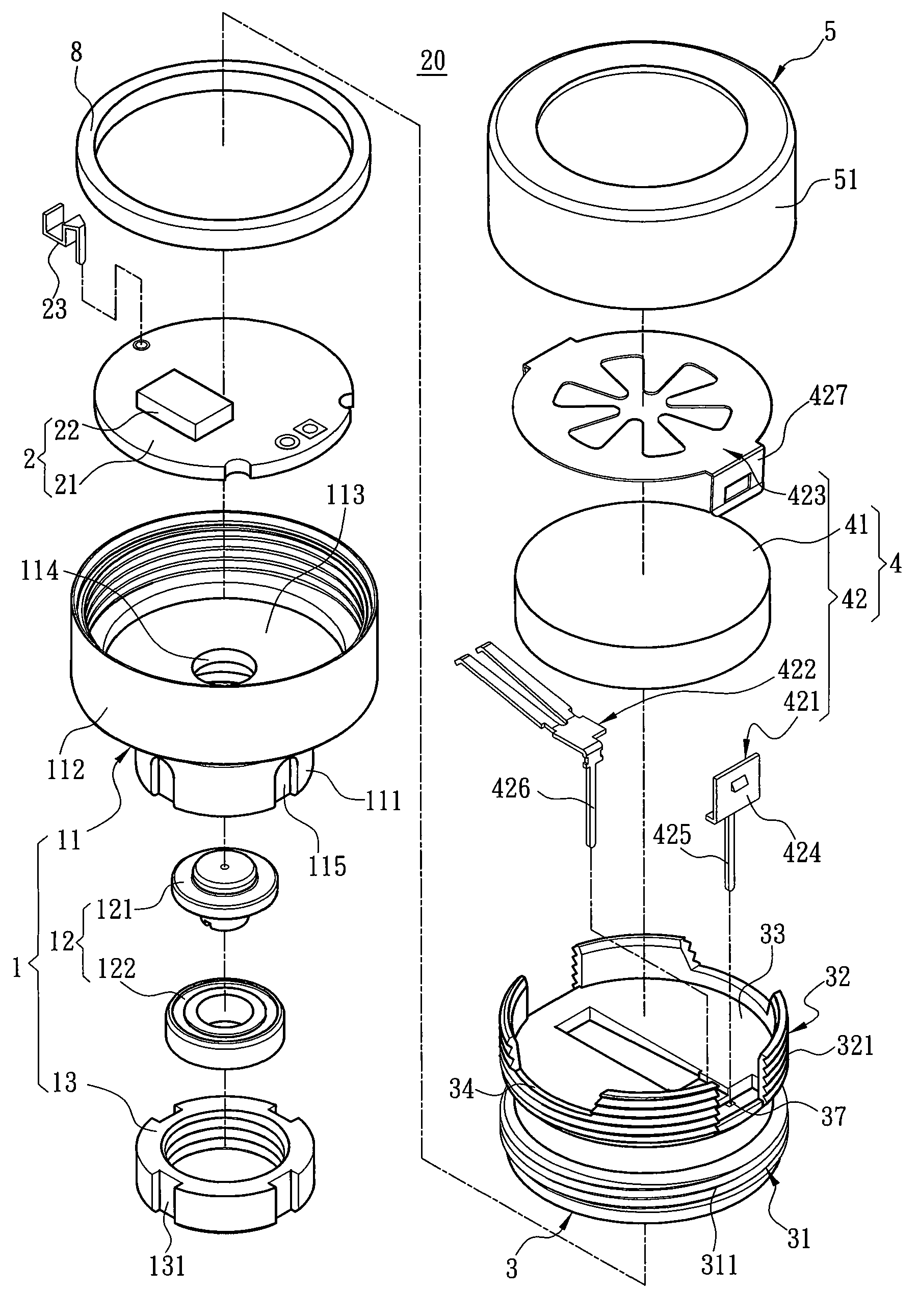
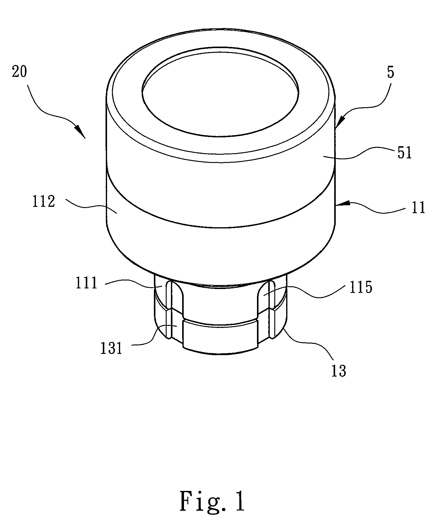
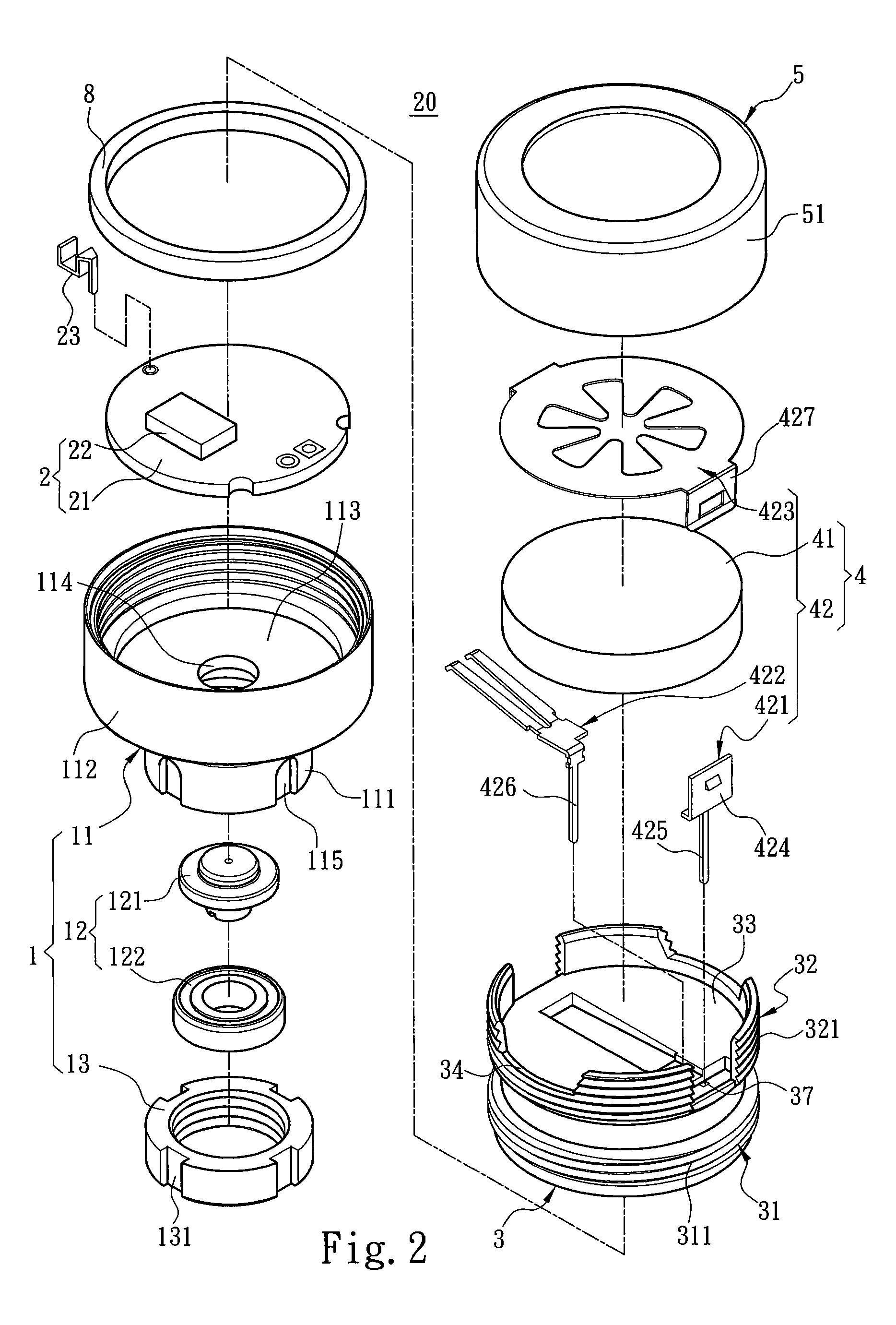
[0020]Refer to FIGS. 1-4 respectively a perspective view, an exploded view, a sectional view, and a diagram schematically showing a tire pressure detector according to the present invention. The present invention proposes a tire pressure detector 20, which is installed on an air tap 10 of a wheel to detect the tire pressure, and which comprises an air-intake device 1, a detection device 2, a bidirectional sleeve 3, a power source 4 and a cap 5.

[0021]The air-intake device 1 includes an air-intake seat 11 and a theft-proof element 13, wherein the air-intake seat 11 and the theft-proof element 13 are made of a metal material. The air-intake seat 11 has an air-intake member 111 and an engagement member 112. A horizontal separator 113 is formed between the air-intake member 111 and the engagement member 112. The horizontal separator 113 has a valve hole 114 interconnecting the air-intake member 111 and the engagement member 112. A valve device 12 props the valve hole 114 against the air ...

second embodiment

[0026]Refer to FIG. 5A and FIG. 5B for the present invention. Refer to FIG. 6A and FIG. 6B for a third embodiment of the present invention. The structures and principles of the second and third embodiments are basically similar to those of FIG. 2. In FIG. 5A and FIG. 5B, the first connection member 31 of the bidirectional sleeve 3 has an inclined face 312 used to press-fit to the engagement member 112 of the air-intake seat 11. The adhesive 36 is used to seal the gap in the junction of the bidirectional sleeve 3 and the air-intake seat 11. In FIG. 6A and FIG. 6B, the second connection member 32 of the bidirectional sleeve 3 has an inclined face 322 used to press-fit to the connection wall 51 of the cap 5. The positive conductor 421 in FIG. 6A and FIG. 6B directly contacts the positive of the battery 41 and thus is slightly different from the positive conductor 421 in FIG. 2. Therefore, the conduction element 42 of the power source 4 needs only the positive conductor 421 and the nega...


PUM


Abstract

A tire pressure detector, which is installed on an air tap of a wheel to detect the tire pressure, comprises an air-intake device, a bidirectional sleeve and a cap. The air-intake device includes an air-intake seat. The air-intake seat has an air-intake member and an engagement member. The air-intake seat is installed on the air tap via the air-intake member. The bidirectional sleeve has a first connection member and a second connection member, which are respectively formed on two sides of a separating member. The first connection member engages with the engagement member of the air-intake seat to form an air chamber accommodating a detection device detecting the tire pressure. The cap has a connection wall, which cooperates with the second connection member to form an accommodation space receiving a power source powering the detection device.

Description

FIELD OF THE INVENTION[0001]The present invention relates to a tire pressure detector, particularly to a tire pressure detector for vehicle wheels.BACKGROUND OF THE INVENTION[0002]Driving safety is the most important matter for drivers, and tires play a significant role in driving safety. The tire of a wheel should have an appropriate pressure. Too high a tire pressure or too low a tire pressure affects driving safety. However, the driver cannot learn the tire pressure from the appearance thereof but can only rely on the equipment and personnel of a vehicle repair shop. Needless to say, the driver cannot monitor the tire pressure in a running vehicle. Therefore, the related manufacturers have developed various tire pressure detectors to monitor the tire pressure.[0003]A R.O.C. patent No. M315663 disclosed a “Detective Air Tap Cap Assembly”, which comprises a casing, a cap, a power supply device, and a detective circuit board. The cap is embedded in on side of the casing, and the det...

Claims


Application Information

Patent Timeline
Patent Type & Authority Patents(United States)
IPC IPC(8): B60C23/02
CPCB60C23/0408B60C23/0496
Inventor HUANG, WEN-HUO
Owner SUNG JUNG MINUTE IND
Why Eureka
Try Eureka