Landing illuminance regulating and controlling device based on infrared monitoring and driving and controlling system thereof

An infrared monitoring and control device technology, applied in energy-saving control technology, electrical components, etc., can solve problems such as insufficient clarity, inability to monitor device scene clear monitoring, scene content is not clear enough, etc., to achieve the effect of reducing lighting power consumption

Inactive Publication Date: 2020-12-11
安徽天达网络科技有限公司
View PDF0 Cites 1 Cited by
  • Summary
  • Abstract
  • Description
  • Claims
  • Application Information

AI Technical Summary

Problems solved by technology

[0002] In some outdoor scenes and courtyards such as factories and docks, some items will be placed, and certain security monitoring needs to be carried out on these items. However, due to the large area of ​​these outdoor scenes, the density of monitoring devices installed is low, and the light at night is poor. In some cases, the monitoring device does not have sufficient monitoring clarity for many areas. Even if an abnormal situation is detected, the content of the monitored scene is not clear enough, and the clarity is insufficient when viewing the display.
[0003] In the existing outdoor scene, large-scale lighting is installed to illuminate the entire outdoor scene area, but only the entire area is illuminated. When an abnormal situation occurs in a local location, it is still impossible for the monitoring device to perform clear monitoring of the scene.
[0004] If a lot of distributed high-brightness lights are used for global lighting, it will obviously cause a lot of waste of electric energy

Method used


Image

  • Landing illuminance regulating and controlling device based on infrared monitoring and driving and controlling system thereof
  • Landing illuminance regulating and controlling device based on infrared monitoring and driving and controlling system thereof
  • Landing illuminance regulating and controlling device based on infrared monitoring and driving and controlling system thereof

Examples


Embodiment 1

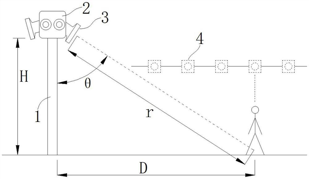
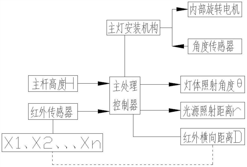
[0041] In the present invention, relates to a floor-based illumination control devices infrared monitoring apparatus in the present invention: a main pole body mounted with the upper end of the main lamp mounting mechanism 2, the lamp 2 is mounted on the movable mounting means is provided with a number of independent straight spotlights 3, the linear spot within the irradiation range of the scene 3 is provided with a number of human infrared sensor 4, the lamp mounting means 2 is provided for adjusting the linear spot built inside the rotary electric machine 3 rotates vertically adjustable.

[0042]The main lamp mounting mechanism 2 is provided with an angle sensor for monitoring the angle of direct light 3 rotation adjustment angles. The angle of direct light 3 on the main lamp mounting mechanism 2 and the angle between the main lamp lever 1 is (0 °, 90 °).

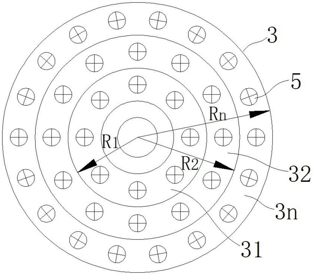
[0043] Direct light 3 is a disc-shaped lamp body, and a number of illumination ring is provided on the direct light 3; eac...


PUM


Abstract

The invention discloses a landing illuminance regulation and control device based on infrared monitoring and a drive and control system thereof, and relates to the technical field of security and protection illumination. According to the invention, the main processing controller obtains the illuminance information of the current direct illuminating lamp, analyzes and compares the illuminance information with the landing illuminance parameter information required by the current position of the human body, adjusts and controls the illuminance of the illuminating lamp of the corresponding ring layer of the direct illuminating lamp, and adjusts and controls the number of the illuminating ring layers of the illuminating lamp of the corresponding ring layer of the direct illuminating lamp. And the main processing controller acquires real-time information monitored by the human body infrared sensor in the scene and performs normalized adjustment on the illumination power of the direct illumination lamp after the action signal is removed. According to the invention, actual distance demand matching adjustment is carried out on the floor illuminance by adjusting the illumination intensity ofthe direct illumination lamp, high-definition illumination is carried out on an abnormal area, an abnormal condition is discovered timely and clearly, the illumination power loss is reduced to a certain extent, and the illumination process is more energy-saving.

Description

Technical field [0001] The present invention belongs to the technical field of security lighting, particularly to a floor-based illumination control devices and infrared monitoring system actuation. Background technique [0002] In some plants outdoor scenes, pier, the compound, some items will be placed, the need for some security monitoring of these items, the monitoring device but due to the lower regions of these larger outdoor scenes mounting density, poor lighting at night under the circumstances, the monitoring device to monitor the lack of clarity of many regions, even if the content of the scene to monitor anomalies, monitored also not clear enough, lack of clarity when viewing the display. [0003] When the conventional outdoor scene, lighting installation of large, outdoor scenes illuminated the entire area, only the entire illuminated area, the local position of the abnormal situation, so that the monitoring device is still not clear of a scene monitoring. [0004] If...

Claims


Application Information

Patent Timeline
Patent Type & Authority Applications(China)
IPC IPC(8): H05B47/13
CPCH05B47/13Y02B20/40
Inventor 李让剑
Owner 安徽天达网络科技有限公司
Why Eureka
Try Eureka