
A LED floodlight with simple structure and easy assembly

A technology for LED floodlights and lamp bodies, which is applied to components, light sources, and electric light sources of lighting devices, and can solve problems such as slippage between the screw and the screw hole of the lamp body, abnormal changes in the angle of the lamp body, and inaccurate structural positioning. , to achieve the effect of reducing production process links, beautiful appearance and guaranteed service life

Active Publication Date: 2017-01-18
中山市领航光电科技有限公司
View PDF5 Cites 0 Cited by
  • Summary
  • Abstract
  • Description
  • Claims
  • Application Information

AI Technical Summary

Problems solved by technology

[0002] LED floodlights have high requirements for angle adjustment, that is, they need to maintain sufficient stability in the case of large-angle adjustments, but the current LED floodlights do not do well in this regard, the main reason is that Determined by the structure, the general LED floodlight is mainly composed of a lamp body, a handle and a bolt. There are screw holes on both sides of the lamp body to cooperate with the bolt. The bolt locks the handle and the lamp body through the bearing. When the angle needs to be adjusted , loosen the bolt, then rotate the relative angle between the lamp body and the handle, and then lock it with the bolt. This structure can meet the stability requirements in the initial stage of the product, but as the use time becomes longer, the screw and the lamp body It is easy to slip between the screw holes, resulting in abnormal changes in the angle of the lamp body; in addition, the simple positioning of the above structure is not accurate, and the angle can only be adjusted by human feeling

Method used


Image

  • A LED floodlight with simple structure and easy assembly
  • A LED floodlight with simple structure and easy assembly
  • A LED floodlight with simple structure and easy assembly

Examples


Embodiment Construction

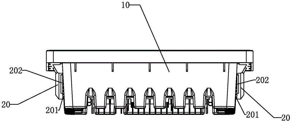
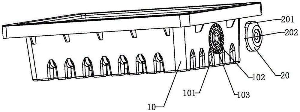
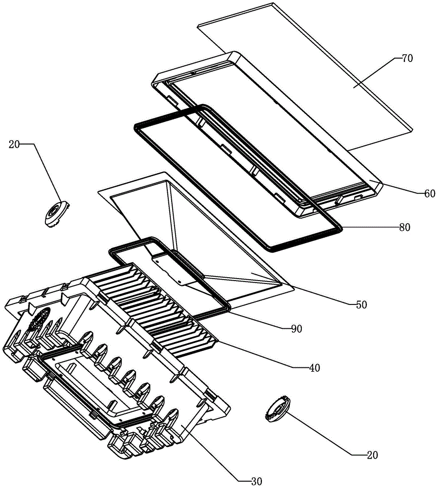
[0023] Such as figure 1 , figure 2 As shown, it is a simple and easy-to-assemble LED floodlight of the present invention, including a lamp body 10, a handle (not shown), two bearings 20 and two bolts (not shown), the lamp The two opposite outer walls of the body 10 are respectively provided with a screw hole 102, and the end of the handle is provided with a through hole, and the bolt passes through the bearing 20, and the through hole at the end of the handle cooperates with the screw hole 102 to lock the lamp body. 10 with handle;

[0024] The outer wall of the lamp body 10 is provided with a gear ring 101 located outside the screw hole 102 and coaxial with the screw hole 102, and the bearing 20 is a cover structure with an open bottom, such as Figure 4 , the outer edge of the bottom of the bearing 20 is provided with a gear arc 201, the arc of the gear arc 201 is not less than 180°, the gears on the gear arc 201 can mesh with the gears on the gear ring 101 for the lamp b...


PUM


Abstract

The invention discloses an LED flood light simple in structure and easy to assemble. The LED flood light comprises a light body, a handle, two bearings and two bolts, wherein a bolt hole is formed in each of two opposite outer side walls of the light body; a through hole is formed in the end part of the handle; the bolts penetrate through the bearings and the through hole in the end part of the handle and are matched with the bolt holes to lock the light body and the handle; gear rings positioned on outer sides of the bolt holes and coaxial with the bolt holes are arranged on the outer side walls of the light body; the bearings adopt cover body structures provided with bottom openings; gear arcs are arranged on bottom outer edges of the bearings; gears on the gear arcs can be meshed with those on the gear rings to realize angle positioning of the light body and the handle; a side hole is formed in a side wall of each bearing; the size of the side hole is the same as that of the end part of the handle, so that the handle can enter the bearings adopting the cover body structures. According to the LED flood light, the bearings used for fixing the handle adopt plastic dense gear type structures, the handle can be randomly adjusted within an angle range of 180 degrees, and an illumination angle of the flood light can be accurately adjusted after the flood light is slightly locked, so that the LED flood light is very convenient to use.

Description

technical field [0001] The invention relates to an LED lamp, in particular to an LED flood lamp with a simple structure and easy assembly. Background technique [0002] LED floodlights have high requirements for angle adjustment, that is, they need to maintain sufficient stability in the case of large-angle adjustments, but the current LED floodlights do not do well in this regard, the main reason is that Determined by the structure, the general LED floodlight is mainly composed of a lamp body, a handle and a bolt. There are screw holes on both sides of the lamp body to cooperate with the bolt. The bolt locks the handle and the lamp body through the bearing. When the angle needs to be adjusted , loosen the bolt, then rotate the relative angle between the lamp body and the handle, and then lock it with the bolt. This structure can meet the stability requirements in the initial stage of the product, but as the use time becomes longer, the screw and the lamp body It is easy to...

Claims


Application Information

Patent Timeline
Patent Type & Authority Patents(China)
IPC IPC(8): F21S8/00F21V31/00F21V17/00F21V14/00F21Y115/10
CPCF21S8/00F21V7/00F21V14/00F21V17/164F21V31/00F21Y2101/00
Inventor 彭继辉
Owner 中山市领航光电科技有限公司
Learn More