Safety speed reducer for roller skates

A deceleration device and roller skate technology, applied to roller skates, ice skating, skateboards, etc., can solve problems such as lack of high-speed active braking, user casualties, etc., to improve speed reduction efficiency, improve safety, and improve friction performance effect

Active Publication Date: 2020-12-15
佛山市顺德区圣顺体育用品有限公司
View PDF5 Cites 6 Cited by
  • Summary
  • Abstract
  • Description
  • Claims
  • Application Information

AI Technical Summary

Benefits of technology

This patented technology describes a new type of safety system used by skiers that prevents them from rolling too quickly or overheated due to excessive speeds caused by their movements. It uses a special part called a recess within the shoe's boot itself, allowing the rotating parts (the eccents) outside the footwear to fit into this space without interferring with any other components like springs or motors. Additionally, there may also include flipper blocks placed under certain conditions to increase traction force while reducing resistance against turning back spinning. Overall, these technical improvements help ensure better control and security during training sessions.

Problems solved by technology

The technical problem addressed in this patented technology relating to rolling wheelskate designs that lack any type of effective anti-brake feature can lead people from accidents caused by too much or too little gearing on their wheels when they stand still at rest after being used with them.

Method used


Image

  • Safety speed reducer for roller skates
  • Safety speed reducer for roller skates
  • Safety speed reducer for roller skates

Examples


Embodiment Construction

[0024] The present invention will be further described below in conjunction with the accompanying drawings and embodiments.

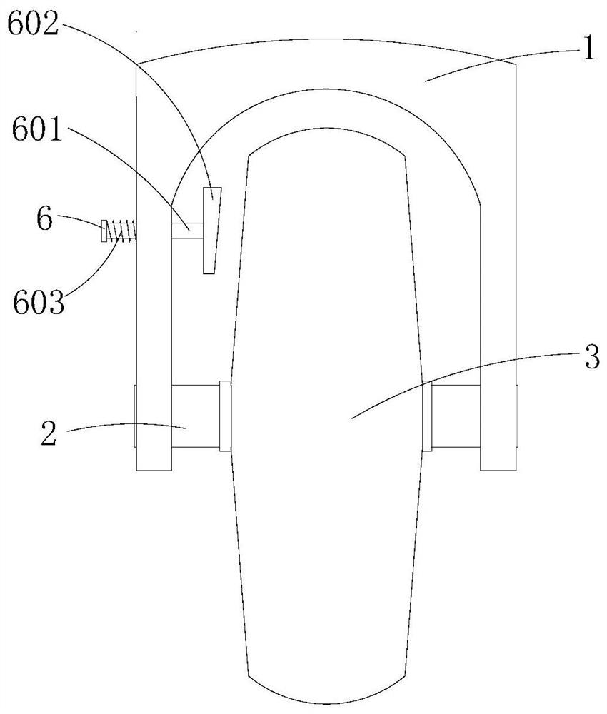
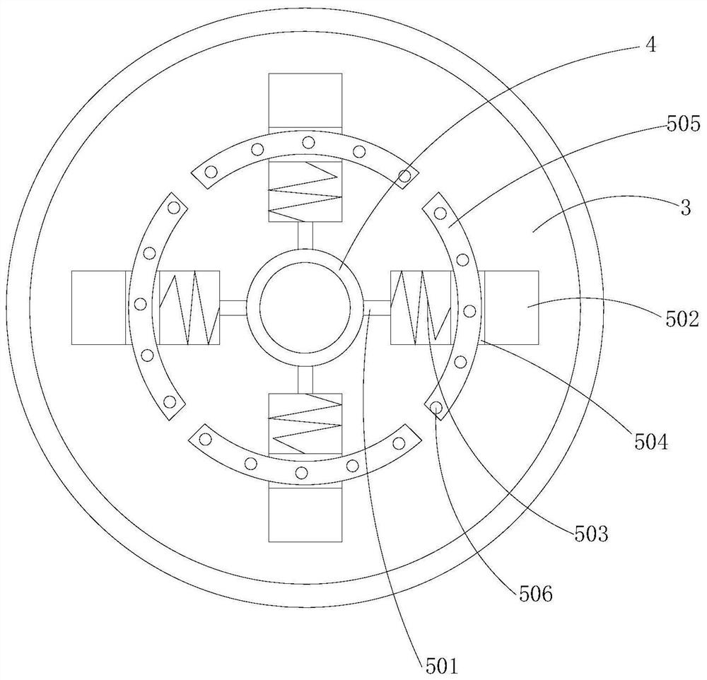
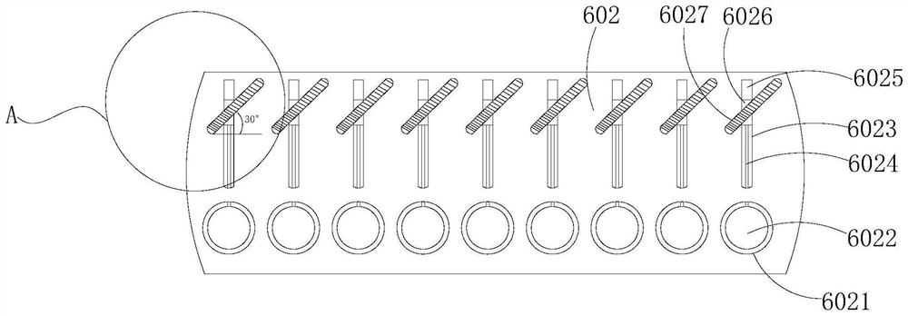
[0025] An embodiment of the present invention provides a safety deceleration device for roller skates, such as Figure 1-5 As shown, including the wheel frame 1, the bottom of the wheel frame 1 is fixedly connected with the wheel shaft 2 through the bearing, the outer surface of the wheel shaft 2 is fixedly sleeved with the sleeve 4, the outer surface of the sleeve 4 is fixedly connected with the roller 3, and the sleeve 4 A centrifugal movement mechanism 5 is fixedly connected to the outer surface and located inside the roller 3 , and a braking device 6 is connected to the wheel frame 1 .

[0026] The centrifugal moving mechanism 5 comprises a connecting column 501, a movable cavity 502, a return spring 503, a centrifugal slider 504, an arc block 505 and a permanent magnet block 506, and the outer surface of the sleeve 4 is fixedly connected with the c...


PUM


Abstract

The invention provides a safety speed reducer for roller skates, and relates to the field of roller skating. The safety speed reducer for the roller skates comprises a wheel frame; a wheel shaft is fixedly connected to the bottom of the wheel frame through a bearing; a sleeve is fixedly connected to the outer surface of the wheel shaft in a sleeving mode; a roller is fixedly connected to the outersurface of the sleeve; a centrifugal moving mechanism is fixedly connected to the outer surface of the sleeve and located in the roller; and the wheel frame is connected with a brake device. According to the safety speed reducer for the roller skates, when the rotating speed of the roller is increased, a centrifugal sliding block in a movable cavity can move away from the sleeve, an arc-shaped block can be driven to do centrifugal motion through centrifugal movement of the centrifugal sliding block, when a permanent magnet block arranged on the arc-shaped block moves to the position where a magnet column is relatively flush, the permanent magnet block and the magnet column are opposite in magnetic pole, magnetic attraction can be generated, and a brake pad can be driven to make contact with the side face of the roller to brake the roller, so that deceleration operation of each roller skate during high-speed movement is effectively achieved, and the safety during movement is improved.

Description


Claims


Application Information

Patent Timeline
Owner 佛山市顺德区圣顺体育用品有限公司
Why Eureka
Try Eureka