
Insert injection molding robot

A technology of insert injection molding and robotics, applied in the field of robotics, can solve the problem that the side of the ball cannot be completely wrapped

Inactive Publication Date: 2020-12-18
高那
View PDF0 Cites 0 Cited by
  • Summary
  • Abstract
  • Description
  • Claims
  • Application Information

AI Technical Summary

Problems solved by technology

[0003] If two metal ball workpieces with smooth appearance are placed inside the mold groove of the insert injection molding robot to make the internal weight of the yo-yo, and the injection tube injects molten plastic into the middle of the two metal balls, the two The metal ball rolls to both sides, and when the ball rolls to fit the inner wall of the mold groove, the side of the ball will not be completely wrapped inside the plastic product

Method used


Image

  • Insert injection molding robot
  • Insert injection molding robot
  • Insert injection molding robot

Examples

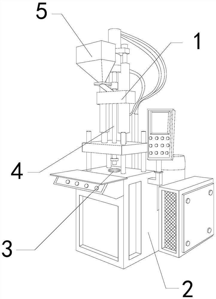
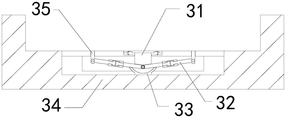

Embodiment 1

[0026] For example figure 1 -example Figure 5 Shown:

[0027] The invention provides an insert injection molding robot, the structure of which includes a support frame 1, a base 2, a mold groove 3, an injection pipe 4, and a heating bucket 5. The support frame 1 is embedded and connected to the upper end of the base 2, and the injection pipe 4 is welded with the support frame 1, the heating bucket 5 is connected with the injection pipe 4, the mold groove 3 and the base 2 are an integrated structure; the mold groove 3 includes a force-bearing block 31, a linkage frame 32, a fixing seat 33. Frame body 34, blocking mechanism 35, the force-bearing block 31 and the middle part of the frame body 34 are in clearance fit, one end of the linkage frame 32 is connected to the blocking mechanism 35, and the other end of the linkage frame 32 is connected to the frame body 34 The inner wall is hingedly connected, the fixed seat 33 and the frame body 34 are an integrated structure, and th...

Embodiment 2

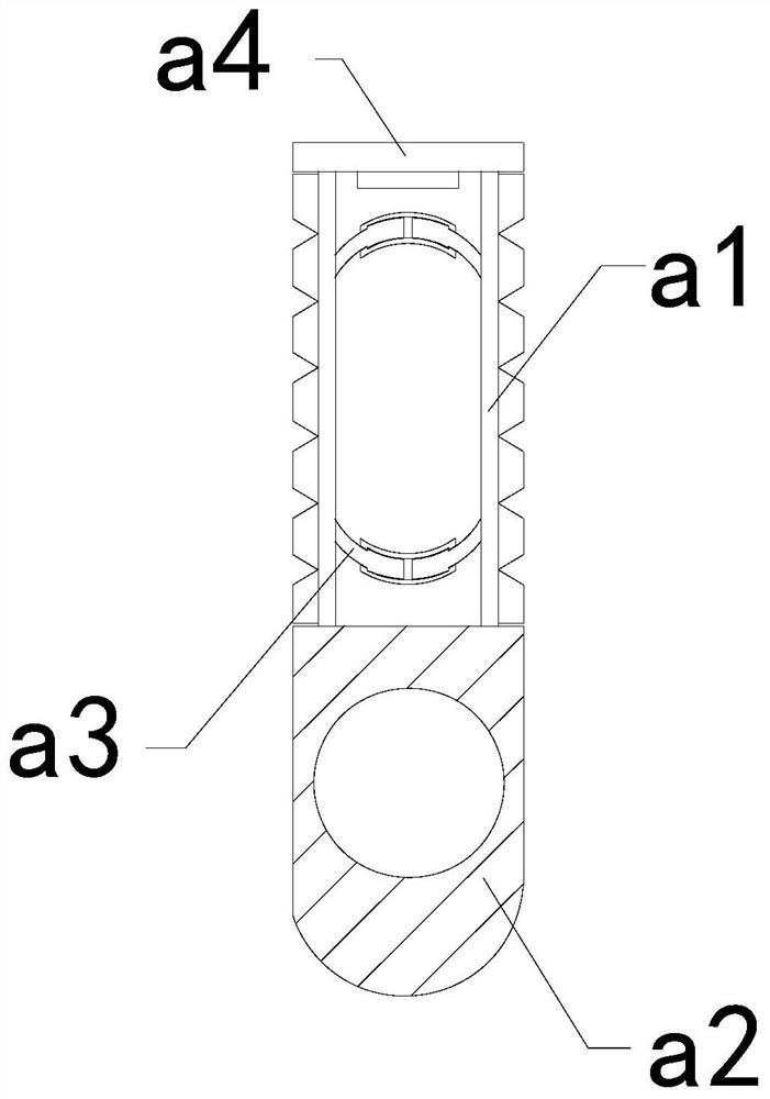
[0034] For example Figure 6 -example Figure 8 Shown:

[0035] Wherein, the upper connection plate a4 includes a sliding plate c1, a guide frame c2, and a pull-back bar c3, the slide plate c1 is movably engaged with the guide frame c2, and the pull-back bar c3 is installed between the two slide plates c1 There are two sliding plates c1, which are evenly distributed symmetrically on the pedestal c2, and the sliding plate c1 can slide to both sides through the thrust generated by the plastic material on the sliding plate c1.

[0036]Wherein, the sliding plate c1 includes a contact plate c11, an upper extension plate c12, a base plate c13, and a connecting frame c14, the contact plate c11 is embedded and connected with the upper end of the upper extension plate c12, and the upper extension plate c12 is connected with the base plate c13 is movable and engaged, and the connecting frame c14 is installed between the base plate c13 and the upper extension plate c12, and the connect...


PUM


Abstract

The invention discloses an insert injection molding robot which structurally comprises a supporting frame, a base, a mold groove, an injection molding pipe and a heating hopper, wherein the supportingframe is fixedly connected with the upper end of the base in an embedded mode, the injection molding pipe is welded to the supporting frame, the heating hopper communicates with the injection moldingpipe, and the mold groove and the base are of an integrated structure. Through the impact force of molten plastic extruded by the injection molding pipe on a stress block, metal balls can be wrappedby the molten plastic in situ, so that the situation that the two metal balls roll towards the two sides when the molten plastic is injected into the middles of the two metal balls by the injection molding pipe is effectively avoided, and through pushing force generated between two sliding plates by the molten plastic, the sliding plates can slide towards the two sides along a guide frame, when aplastic product is taken out upwards after being solidified, and the two sliding plates can be pulled by a pull-back strip to slide towards the middle, so that separation blocks can swing upwards to scrape off and separate the bottom of the plastic from the upper surface of an upper connecting plate.

Description

technical field [0001] The invention relates to the field of robots, in particular to an insert injection molding robot. Background technique [0002] The insert injection molding robot is mainly used for the production of insert plastic products. It can heat the plastic raw materials into molten plastic through the heating bucket, and then inject the molten plastic vertically downward into the mold groove through the injection tube, so that The metal or non-metal workpiece placed in the mold groove can be wrapped in advance, and the insert plastic product can be obtained after being cooled and solidified. Based on the above description, the inventors found that the existing insert injection molding robot mainly has the following deficiencies: For example: [0003] If two metal ball workpieces with smooth appearance are placed inside the mold groove of the insert injection molding robot to make the internal weight block of the yo-yo, and the injection tube injects molten pl...

Claims


Application Information

Patent Timeline
Patent Type & Authority Applications(China)
IPC IPC(8): B29C45/14B29C45/40
CPCB29C45/14819B29C45/4005
Inventor 高那
Owner 高那
Learn More