Glass lining equipment firing frame

A glass-lined and equipment technology, applied in the field of glass-lined equipment firing frames, can solve problems such as adhesion, glass-lined difficult to remove directly, enamel fixed on, etc.

Inactive Publication Date: 2021-03-09
陈俊翔
View PDF0 Cites 0 Cited by
  • Summary
  • Abstract
  • Description
  • Claims
  • Application Information

AI Technical Summary

Problems solved by technology

[0003] Since the carrier plate on the glass-lined firing frame is composed of multiple cross bars, and the glass-lined glass is fired by coating the enamel with high silicon content on the metal surface, if the metal surface is just coated with enamel, it is placed on the carrier plate , it is easy to make the enamel adhere to the carrier plate, and when the firing is completed, the enamel will be fixed on the crossbar of the carrier plate, making it difficult to remove the glass lining directly from the carrier plate

Method used


Image

  • Glass lining equipment firing frame
  • Glass lining equipment firing frame
  • Glass lining equipment firing frame

Examples


Embodiment 1

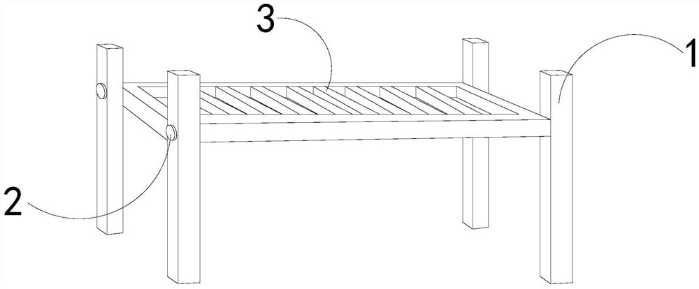
[0026] For example figure 1 -example Figure 5 Shown:

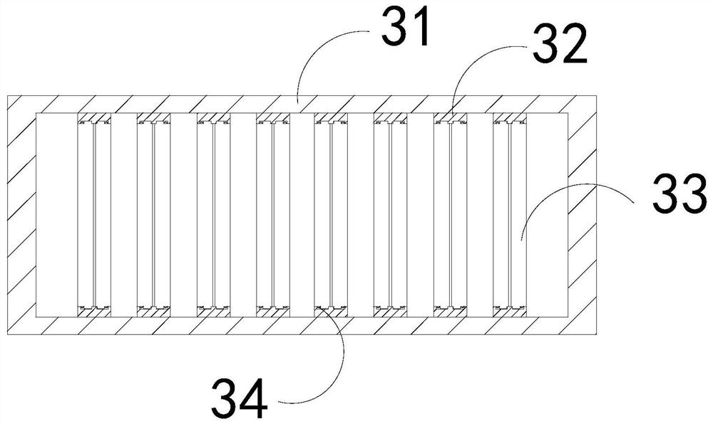
[0027] The present invention provides a firing frame for glass-lined equipment, the structure of which includes a support frame 1, fixing nails 2, and a bearing plate 3. The fixing nails 2 are embedded and connected to the support frame 1, and the bearing plate 3 and the support frame 1 are Integrated structure; the bearing plate 3 includes an outer frame 31, a guide block 32, a receiving plate 33, and a reset piece 34, the guide block 32 and the outer frame 31 are an integrated structure, and the receiving plate 33 and the guide block 32 are movable The reset piece 34 is installed between the receiving plate 33 and the guide block 32 .

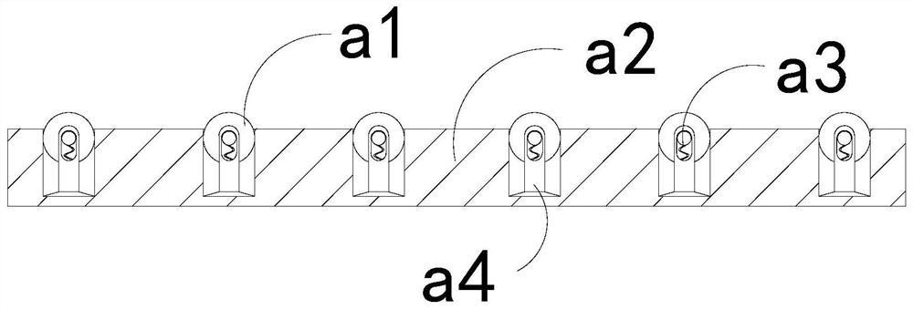
[0028] Wherein, the receiving plate 33 includes a shrinking roller a1, a plate body a2, an elastic strip a3, and a connecting rod a4, the shrinking roller a1 is movably engaged with the connecting rod a4, and the elastic strip a3 is installed on the shrinking roller a1 and the connecti...

Embodiment 2

[0034] For example Figure 6 -example Figure 8 Shown:

[0035] Wherein, the board surface b2 includes a blocking roller b21, an external connecting plate b22, and a guide cavity b23, the blocking roller b21 is movably engaged with the external connecting plate b22, the guiding cavity b23 and the external connecting plate b22 are an integrated structure, and the guiding cavity b23 is integrated with the external connecting plate b22. The cavity b23 has a transparent structure inside and outside, and enamel debris can be introduced into the cavity through the guiding cavity b23.

[0036] Wherein, the blocking roller b21 includes an outer plate c1, an elastic ring c2, a middle solid plate c3, and a middle connecting piece c4. The position of the outer surface of the middle solid plate c3, the middle joint c4 is fixed between the two outer plates c1, the two outer plates c1 are evenly distributed symmetrically outside the middle solid plate c3 , the outer panel c1 can be shrun...


PUM


Abstract

The invention discloses a glass lining equipment firing frame which structurally comprises a supporting frame, a fixing nail and a bearing plate. The fixing nail is fixedly connected with the supporting frame in an embedded mode; the bearing plate and the supporting frame are of an integrated structure; through throwing force generated by rotation of an external ring, an external pushing block canextend outwards and swing under compression of glass lining, so that the glass lining can be slightly lifted, the ceramic glaze between the glass lining and the bearing plate can be torn off, and thesituation that the glass lining is difficult to take down due to the fact that the ceramic glaze coated on the surface of the glass lining is adhered to the bearing plate is effectively avoided; andceramic glaze scraps between an outer push block and a plate surface can be guided into an outer connecting plate through a guide cavity, and an external plate can contract towards the middle part under the matching of an elastic ring through the pushing force generated by the ceramic glaze scraps to a blocking roller, so that the ceramic glaze scraps can be discharged outwards through a gap between the external plate and the outer connecting plate, and the situation that the ceramic glaze scraps enter the outer pushing block and the plate surface and are difficult to discharge outwards is effectively avoided.

Description

technical field [0001] The invention relates to the field of glass equipment, in particular to a firing frame for glass-lined equipment. Background technique [0002] The glass-lined firing frame is mainly used to carry the glass-lined glass. By placing the glass-lined blank on the glass-lined firing frame, and then pushing the glass-lined firing frame into the glass-lined firing furnace, the glass-lined Firing glass blanks is a common equipment in the glass-lined firing industry. Based on the above description, the inventors found that the existing firing frame for glass-lined equipment mainly has the following deficiencies, for example: [0003] Since the carrier plate on the glass-lined firing frame is composed of multiple cross bars, and the glass-lined glass is fired by coating the enamel with high silicon content on the metal surface, if the metal surface is just coated with enamel, it is placed on the carrier plate , it is easy to make the enamel adhere to the carrie...

Claims


Application Information

Patent Timeline
Patent Type & Authority Applications(China)
IPC IPC(8): C23D9/00
CPCC23D9/00
Inventor 陈俊翔
Owner 陈俊翔
Why Eureka
Try Eureka