Actuating mechanism

A technology for actuators and air chambers, applied in mechanical equipment, engine components, engine seals, etc., can solve the problems of unstable sealing of internal parts, inconvenient disassembly and installation work, etc., to achieve convenient maintenance and replacement work, convenient and quick installation Disassembly work, the effect of increasing the safety of use

Pending Publication Date: 2020-12-25
ZHEJIANG JIANJIANG SHIP TECH CO LTD
View PDF0 Cites 1 Cited by
  • Summary
  • Abstract
  • Description
  • Claims
  • Application Information

AI Technical Summary

Problems solved by technology

[0007] The purpose of the present invention is to provide an actuator to solve the problems that the actuators for vacuum toilets currently on the market are inconvenient to disassemble and install and cannot perform stable sealing work on internal parts proposed by the above-mentioned background technology.

Method used


Image

  • Actuating mechanism
  • Actuating mechanism
  • Actuating mechanism

Examples


Embodiment Construction

[0028] The following will clearly and completely describe the technical solutions in the embodiments of the present invention with reference to the accompanying drawings in the embodiments of the present invention. Obviously, the described embodiments are only some, not all, embodiments of the present invention. Based on the embodiments of the present invention, all other embodiments obtained by persons of ordinary skill in the art without making creative efforts belong to the protection scope of the present invention.

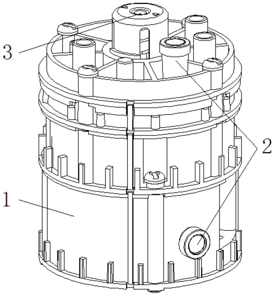
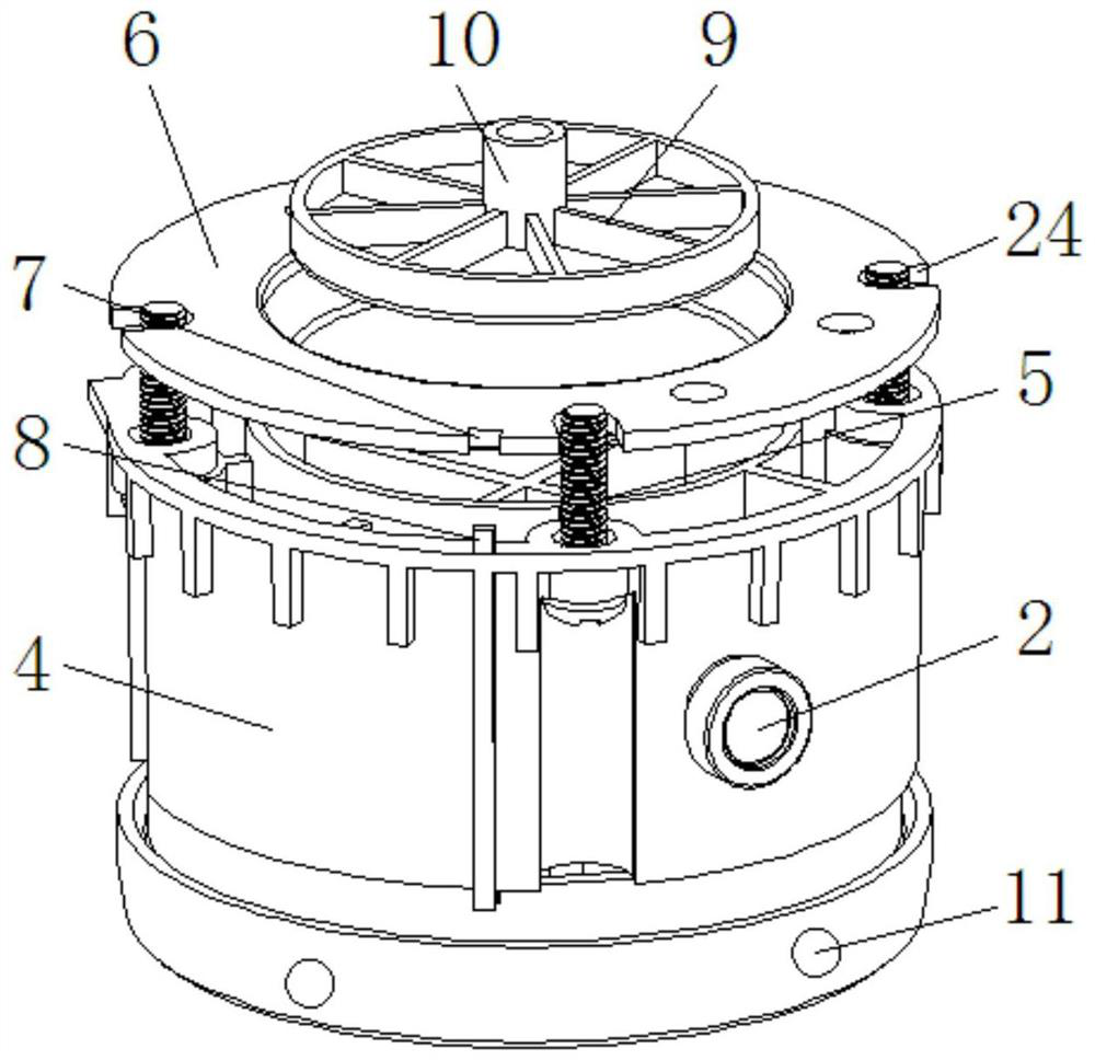
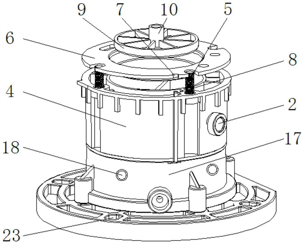
[0029] see Figure 1-8 , the present invention provides a technical solution: an actuator, including an actuator body 1, a damping plug 2, a drive shaft 3, an installation air chamber 4, self-tapping screws 5, a sealing gasket 6, a limit groove 7, and a limit rod 8. Fixed top plate 9, connecting rod 10, card slot 11, mounting plate 12, main rubber airbag 13, connecting hose 14, side rubber airbag 15, limit frame 16, fixed base 17, fixed frame 18, rubber rod 1...


PUM


Abstract

The invention discloses an actuating mechanism. The actuating mechanism comprises an actuating mechanism body, a mounting gas chamber, a side rubber gasbag and a blocking rod, wherein a damping plug is in bolt mounting on the actuating mechanism body; a drive shaft is movably connected on the actuating mechanism body; a mounting plate is in bolt connection in the mounting gas chamber; the top endof the mounting plate is in bolt connection to a main rubber gasbag; a connecting hose is in bolt mounting on the main rubber gasbag; the top end of the connecting hose is in bolt mounting with the side rubber gasbag; and the side rubber gasbag is in bolt connection in the mounting gas chamber. The actuating mechanism is equipped with the side rubber gasbag, the drive shaft drives a fixed top plate to extrude the main rubber gasbag downwards in the mounting gas chamber; and under extrusion effect of the main rubber gasbag, gas is conveyed into the side rubber gasbag through the connecting hosewhile the side rubber gasbag can conveniently and quickly extrude, package and seal the fixed top plate, so that use sealing property of the actuating mechanism is effectively improved.

Description

technical field [0001] The invention relates to the technical field of military vacuum toilets, in particular to an actuator. Background technique [0002] With the continuous development and growth of our country's military power, in order to ensure the territorial security of our country's maritime domain, it is necessary to use a large number of warships to provide take-off and landing of unmanned carrier-based aircraft, and then be able to perform combat missions at sea. In the daily life of combatants, it is necessary to install washing equipment and toilets on warships. Because conventional toilets are not convenient for mobile use on warships, with the continuous development of science and technology, people have invented vacuum toilets. As the name suggests, the entire system of the toilet is in the In a vacuum state, the system must have an isolation valve to isolate each toilet from the system. When the toilet is flushed, this valve is opened, and the contents of t...

Claims


Application Information

Patent Timeline
Patent Type & Authority Applications(China)
IPC IPC(8): B63B29/14F16J15/02
CPCB63B29/14F16J15/022
Inventor 潘建光
Owner ZHEJIANG JIANJIANG SHIP TECH CO LTD
Why Eureka
Try Eureka