Eureka AIR delivers breakthrough ideas for toughest innovation challenges, trusted by R&D personnel around the world.

Improved vertical barrel cutting machine

A barrel cutting machine, vertical technology, applied in the direction of metal processing machinery parts, maintenance and safety accessories, metal processing equipment, etc., can solve problems such as unstable plugging force, user safety accidents, user electric shock, etc., to achieve automation High degree of use, prevent electric shock accidents, increase the effect of service life

Inactive Publication Date: 2018-12-07
广州太牛科技有限公司
View PDF2 Cites 0 Cited by
  • Summary
  • Abstract
  • Description
  • Claims
  • Application Information

AI Technical Summary

Problems solved by technology

[0002] At present, the old metal barrel vertical barrel is usually recycled and cut after use. At present, the metal barrel vertical barrel cutting machine is manually plugged and unplugged by personnel when the power is connected, and the connection part is easily affected by the voltage during the plugging process. Electric arc is generated, and the generation of electric arc is easy to cause electric shock to the user. It has certain potential danger to the user, which will cause safety accidents and cause casualties. Moreover, the force of personnel is unstable when plugging and connecting, which is easy to cause equipment damage. Moreover, the traditional power transmission There is usually no closed protective measure for the power transmission port, and the exposed power transmission port is easy to enter dust, etc., which affects the service life

Method used


Image

  • Improved vertical barrel cutting machine
  • Improved vertical barrel cutting machine
  • Improved vertical barrel cutting machine

Examples


Embodiment Construction

[0018] Combine below Figure 1-4 The present invention will be described in detail.

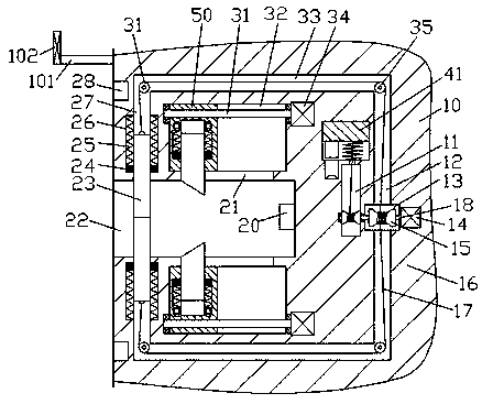
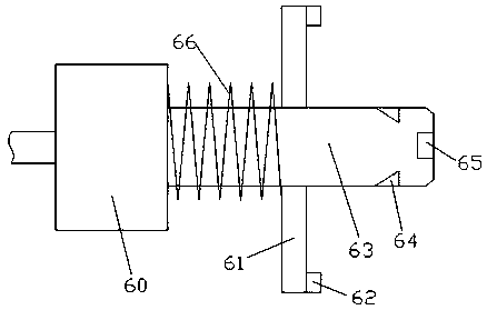
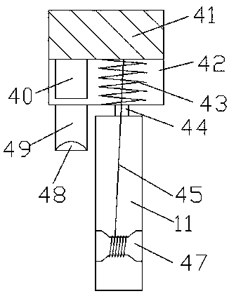
[0019] refer to Figure 1-4 , an improved vertical barrel cutting machine according to an embodiment of the present invention, comprising a main frame body 10 and a coupling part 60 connected to the main frame body 10 by plugging and fitting, the left side of the main frame body 10 The end face is provided with a socket 22, and the inner wall on the right side of the socket 22 is fixed with a power transmission block 20. The upper and lower inner walls of the socket 22 are symmetrically provided with first sliding grooves 27, and the sliding fit in the first sliding groove 27 is A blocking cover 23 is installed, and first guide grooves 26 are symmetrically arranged in the inner walls of the left and right sides of the first sliding groove 27 . The first guide block 24, the side of the first guide block 24 far away from the socket 22 is press-fitted and connected with the first spring pressi...


PUM


Abstract

The invention discloses an improved vertical barrel cutting machine. The improved vertical barrel cutting machine comprises a main frame and a connecting part connected to the main frame in inserted and matched modes. An insertion opening is formed in the end face of the left side of the main frame. A power supply block is fixedly arranged on the inner wall of the right side of the insertion opening. First sliding grooves are symmetrically formed in the upper inner wall and the lower inner wall of the insertion opening. A cover is mounted in the first sliding grooves in a sliding fit mode. First guide grooves are symmetrically formed in the inner walls of the left side and the right side of each first sliding groove. First guide blocks fixedly connected with the cover are mounted in the first guide grooves in a sliding fit mode. A first elastic pressing piece is connected to the side, away from the insertion opening, of each first guide block in an abutting fit mode. A second sliding groove which extends rightwards is formed in the tail end of the side, away from the insertion opening, of each first sliding groove.

Description

technical field [0001] The invention relates to the technical field of vertical barrel processing, in particular to an improved vertical barrel cutting machine. Background technique [0002] At present, the old metal barrel vertical barrel is usually recycled and cut after use. At present, the metal barrel vertical barrel cutting machine is manually plugged and unplugged by personnel when the power is connected, and the connection part is easily affected by the voltage during the plugging process. Electric arcs are generated, and the generation of arcs is likely to cause electric shock to users, which has certain potential dangers to users, which will cause safety accidents and cause casualties, and personnel are unstable in plugging and connecting, which may easily lead to equipment damage. Moreover, traditional power transmission The port is usually not closed and protected, and the exposed power transmission port is easy to enter dust, etc., which affects the service life...

Claims


Application Information

Patent Timeline
Patent Type & Authority Applications(China)
IPC IPC(8): B23Q11/00
CPCB23Q11/0089
Inventor 凌桂福
Owner 广州太牛科技有限公司
Why Eureka
Eureka Blog
Learn More