
Linkage door lock

A linkage and door lock technology, applied in door leaves, building locks, windows/doors, etc., can solve problems such as difficulty in implementation and difficulty in ensuring the reliability of door locks for human life safety.

Inactive Publication Date: 2020-12-29
朱佳甜
View PDF0 Cites 0 Cited by
  • Summary
  • Abstract
  • Description
  • Claims
  • Application Information

AI Technical Summary

Problems solved by technology

[0002] There are many problems and defects in the existing door lock equipment. When opening and closing some relatively large doors, most of them adopt the telescopic sliding method to slide and fold several doors. When the sliding door is locked on both sides, the left and right doors on both sides need to be locked with the help of bolts, and the upper and lower sides of the door and the door frame are also locked. During this process, personnel need to pull the bolts at each position separately. Make the bolts in the door slide and retract into the door. Due to the large number of bolts, the personnel have to slide and twitch many times to slide all the bolts into the door and lock the door in turn. Or open, due to the existence of the above-mentioned shortcomings, if there are not many people who work together when people need to open the door urgently, it will be difficult to realize this process, making it difficult to guarantee the safety of people's lives and the reliability of the door lock.

Method used


Image

  • Linkage door lock
  • Linkage door lock
  • Linkage door lock

Examples


Embodiment Construction

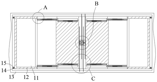
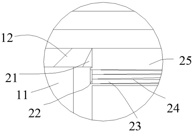
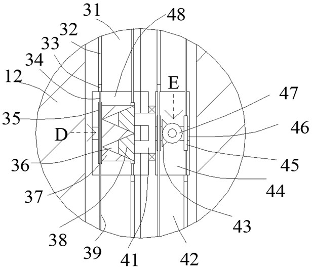
[0022] like Figure 1-Figure 7 As shown, the present invention is described in detail. For the convenience of description, the orientations mentioned below are now stipulated as follows: figure 1 The up, down, left, right, front and back directions of the projection relationship are the same. A linkage door lock of the present invention includes a door frame 13, and a plurality of sliding door panels 12 are arranged inside the door frame 13, and one side of the sliding door panels 12 on both sides is provided with Up and down symmetrical side bumps 15, the door frame 13 is provided with a number of side fixing blocks 14, the side fixing blocks 14 and the side bumps 15 are hingedly arranged, and the sliding door panel 12 is provided with an inner cavity 11, The adjacent sliding door panels 12 protrude into the inner cavity 11 and are slidably connected with them. The end faces of the sliding door panels 12 are provided with an open fixed slope 21, and the fixed slopes 21 are ar...


PUM


Abstract

The invention discloses a linkage door lock. The linkage door lock comprises a door frame; a plurality of sliding door plates are arranged in the door frame; vertically-symmetrical side protruding blocks are arranged on one sides of the sliding door plates located on the two sides; a plurality of side fixing blocks are arranged in the door frame; the side fixing blocks are hinged to the side protruding blocks; inner cavities are formed in the sliding door plates. the adjacent sliding door plates extend into the inner cavities and are connected with the inner cavities in a sliding fit mode; open fixed slopes are arranged on the end faces of the sliding door plates; and the fixed slopes are symmetrically arranged. According to the linkage door lock, the equipment forms the sliding door in amutual sliding mode and can rotate; and moreover, when the lock is unlocked, locking and fixing between the sliding door plates on the two sides and the door frame can be unlocked to avoid the situation that a person unlocks the equipment for many times, so that the purpose of rapid and labor-saving unlocking is achieved.

Description

technical field [0001] The invention relates to the technical field of door lock equipment, in particular to a linkage door lock. Background technique [0002] There are many problems and defects in the existing door lock equipment. When opening and closing some relatively large doors, most of them adopt the telescopic sliding method to slide and fold several doors. When the sliding door is locked on both sides, the left and right doors on both sides need to be locked with the help of bolts, and the upper and lower sides of the door and the door frame are also locked. During this process, personnel need to pull the bolts at each position separately. Make the bolts in the door slide and retract into the door. Due to the large number of bolts, the personnel have to slide and twitch many times to slide all the bolts into the door and lock the door sequentially. Or open, due to the existence of above-mentioned shortcoming, if there is not many personnel to carry out cooperative...

Claims


Application Information

Patent Timeline
Patent Type & Authority Applications(China)
IPC IPC(8): E06B3/36E06B3/46E06B3/50E06B3/70E05D15/06E05C7/04E05C9/12E05C9/04E05C9/18E05C9/22E05C9/00E05B65/08E05B65/00E05B15/00
CPCE05B15/00E05B65/0003E05B65/087E05C7/04E05C9/004E05C9/041E05C9/047E05C9/1808E05C9/22E05D15/0621E06B3/362E06B3/4636E06B3/5054E06B3/509E06B3/70
Inventor 朱佳甜
Owner 朱佳甜
Learn More