Door unlocking controller and control method thereof

a technology for unlocking controllers and doors, applied in the direction of program control, electrical locking circuits, anti-theft devices, etc., can solve the problems of unfavorable door unlocking operation, and new problem of conventional technique b>2/b>

Active Publication Date: 2007-07-17
MITSUBISHI MOTORS CORP
View PDF11 Cites 17 Cited by
  • Summary
  • Abstract
  • Description
  • Claims
  • Application Information

AI Technical Summary

Benefits of technology

[0015]The present invention has been made in view of the above-described problems. Accordingly, it is the primary object of the present invention to provide a door unlocking controller and a control method thereof that are capable of enhancing security by preventing a person not having a portable unit from unlocking a door.
[0017]According to the door unlocking controller of the present invention, under the condition that a person holding a portable unit is near one of the left and right doors of a vehicle, even when another person not having the portable unit inputs a request to unlock the other door, the unlocking of that door is not performed and therefore the unlocking of doors by the person not having the portable unit can be prevented. Thus, vehicle security can be enhanced.
[0025]According to the door-unlocking control method of the present invention, under the condition that a person holding a portable unit is near one of the left and right doors of a vehicle, even when another person not having the portable unit inputs a request to unlock the other door, the unlocking of that door is not performed and therefore the unlocking of doors by the person not having the portable unit can be prevented. Thus, vehicle security can be enhanced.
[0029]In a further preferred form of the method of the present invention, the transmission control step causes the transmission means of the one side portion to transmit the first signal to a first predetermined region having the one side portion as a center thereof, and also causes the transmission means of the other side portion to transmit the second signal to a second predetermined region having the other side portion as a center thereof, and sets power for transmitting the second signal so that the second predetermined region becomes larger than a first leakage region where the first signal leaks out from the other side portion, and so that a second leakage region where the second signal leaks out from the one side portion becomes a minimum region.

Problems solved by technology

Therefore, this does not always meet the unlocking of a door requested by a portable-unit holder, and there is a possibility that an unnecessary door-unlocking operation will be repeated against the intention of a portable-unit holder.
In addition, since it is necessary to always form a wide area around a vehicle, it can not be said to be efficient.
However, the conventional technique 2 has a new problem that is to be described below.
For that reason, there is a possibility that the leakage will cause a new safety problem.
As a result, there is a possibility that vehicle security cannot be ensured.
However, in this case, the portable unit 24 needs to have the function of measuring the strength of an electric field, so it becomes large in size and costly.

Method used


Image

  • Door unlocking controller and control method thereof
  • Door unlocking controller and control method thereof
  • Door unlocking controller and control method thereof

Examples


first embodiment

(A) FIRST EMBODIMENT

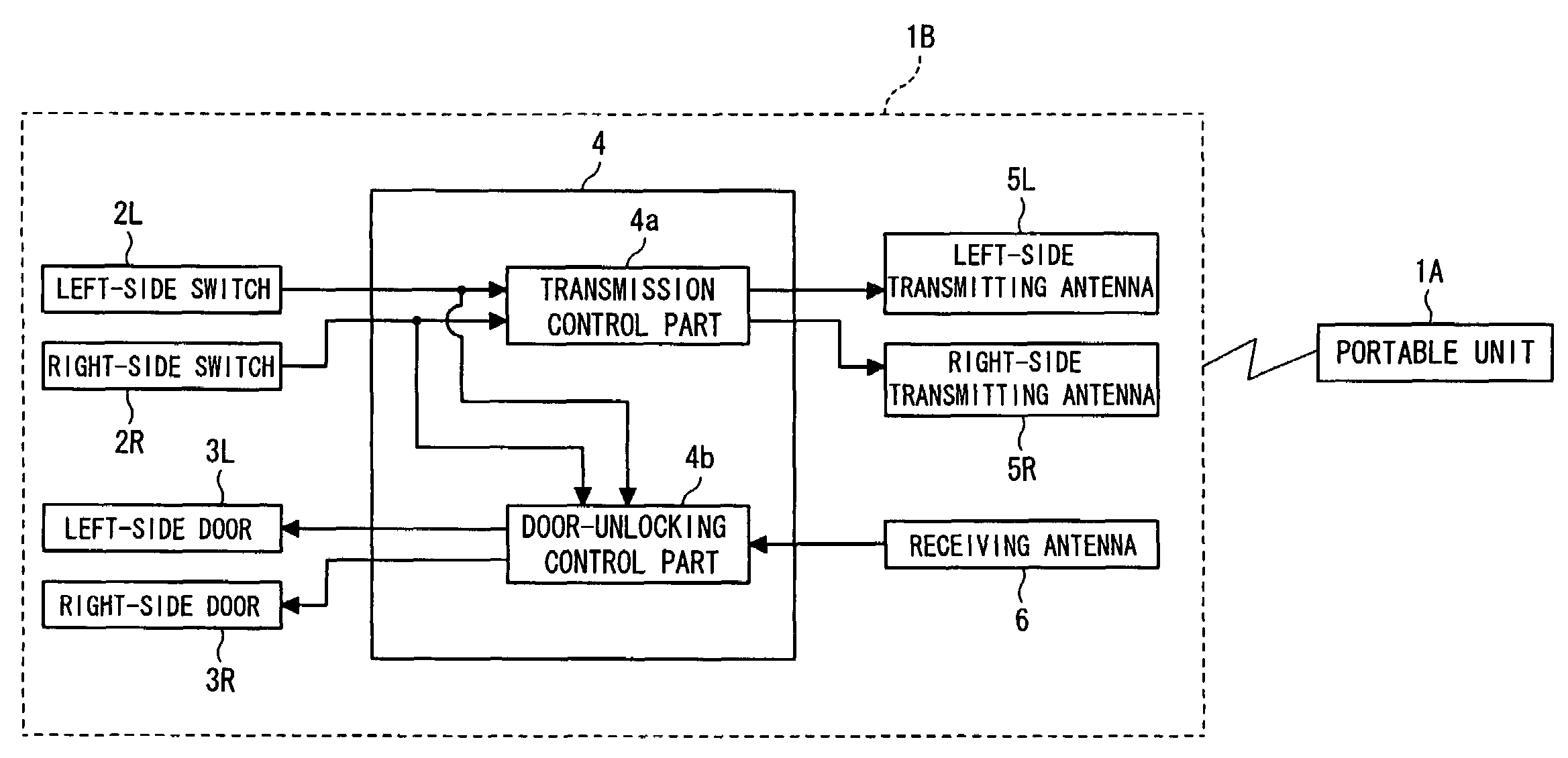
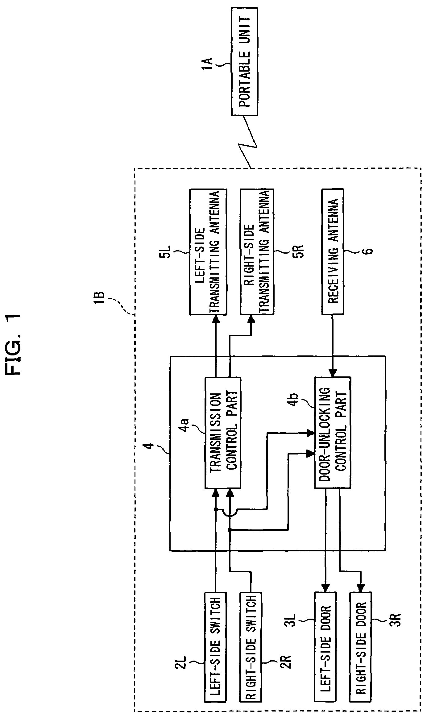
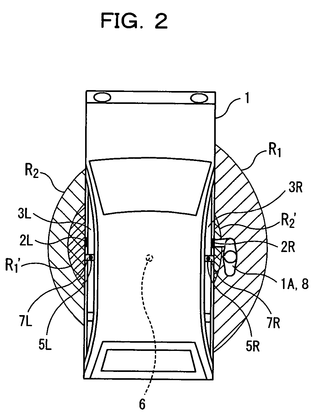
[0039]Referring to FIGS. 1 and 2, there is shown a door unlocking controller for a vehicle constructed in accordance with a first embodiment of the present invention.

[0040]FIG. 1 is a block diagram and FIG. 2 is a top view showing a door unlocking controller for a vehicle. As shown in the figures, the door unlocking controller according to this embodiment is a door unlocking controller for a vehicle 1, which controls the unlocking of the left-side door 3L and right-side door 3R of the vehicle 1 by checking if the vehicle ID given to the vehicle 1 corresponds to the portable-unit ID given to a portable unit 1A. The door unlocking controller is equipped with a vehicle-side system 1B, and a portable unit 1A capable of transmission and reception. The vehicle-side system 1B mainly includes door switches (input means) 2L and 2R, an electronic control unit (ECU) 4 having functions equivalent to a transmission control part (transmission control means) 4a and a door-unloc...

second embodiment

(B) SECOND EMBODIMENT

[0058]A description will hereinafter be given of a door unlocking controller constructed in accordance with a second embodiment of the present invention.

[0059]In the first embodiment, if the portable unit 1A receives an ID request signal and does not receive an alarm signal, a portable-unit signal is sent back from the portable unit 1A. In the second embodiment, if an ID request signal is received as a portable-unit signal (third signal), an ID-request-received signal (fourth signal) containing portable-unit ID is sent back. Also, if an alarm signal is received, an alarm-received signal (fifth signal) is sent back.

[0060]That is, in the first embodiment, even if the portable unit 1A receives an ID request signal, it does not send back a portable-unit signal if it receives an alarm signal. However, in the second embodiment, even if the portable unit 1A receives an alarm signal, a portable-unit signal is sent back. In addition, at least either the above-described I...


PUM


Abstract

When a request to unlock a door of one side portion of a vehicle is input, an ID request signal is transmitted from a first transmitting antenna provided in the one side portion, and an alarm signal is transmitted from a second transmitting antenna provided in the other side portion of the vehicle. A portable unit sends back a portable-unit signal in dependence on the ID request signal and alarm signal. When the portable unit receives the first signal and does not receive the second signal, a door-unlocking control part unlocks the door of the one side portion in dependence on the portable-unit signal received by a receiving antenna.

Description

CROSS-REFERENCE TO RELATED APPLICATION[0001]This application incorporates by references the subject matter of Application No. 2003-297512 filed in Japan on 21 Aug. 2003, on which a priority claim is based under 35 U.S.C. §119(a).BACKGROUND OF THE INVENTION[0002]1. Field of the Invention[0003]The present invention relates to a door unlocking controller and a control method thereof, which control the unlocking of doors of a vehicle in dependence on a signal from a portable unit.[0004]2. Description of the Related Art[0005]Door unlocking controllers have been developed, which control the unlocking of doors of a vehicle such as an automobile without using a mechanical key or remote control key.[0006]For instance, Japanese Laid-Open Patent Publication No. 2000-73635 discloses a conventional technique 1, in which a wide area capable of receiving a wide-area ID request signal is formed around a vehicle by an electronic radio wave whose operating range is relatively wide. If a portable unit...

Claims


Application Information

Patent Timeline
Patent Type & Authority Patents(United States)
IPC IPC(8): H04Q9/00H04Q5/22E05B49/00B60R25/01B60R25/24B60R25/31G07C9/00
CPCB60R25/245G07C9/00309G07C2009/00333G07C2209/63E05B81/76E05B81/60
Inventor INOGUCHI, TOHRU
Owner MITSUBISHI MOTORS CORP
Why Eureka
Try Eureka