Smart entry system

Inactive Publication Date: 2005-11-17
DENSO CORP
View PDF11 Cites 17 Cited by
  • Summary
  • Abstract
  • Description
  • Claims
  • Application Information

AI Technical Summary

Benefits of technology

[0034] That is, the unlocking only the specific door and the unlocking plural doors containing the specific door can be rapidly performed. As a specific method, only the specific door corresponding to the touch detecting u

Problems solved by technology

However, if all the doors are unlocked by switch operation on the door unlock switch, a stranger (unauthorized person) may get into the vehicle from the assistant driver's seat side when an authorized user gets into the driver's seat after the doors are unlocked.
However, when it is required to unlock the door

Method used


Image

  • Smart entry system
  • Smart entry system
  • Smart entry system

Examples


first embodiment

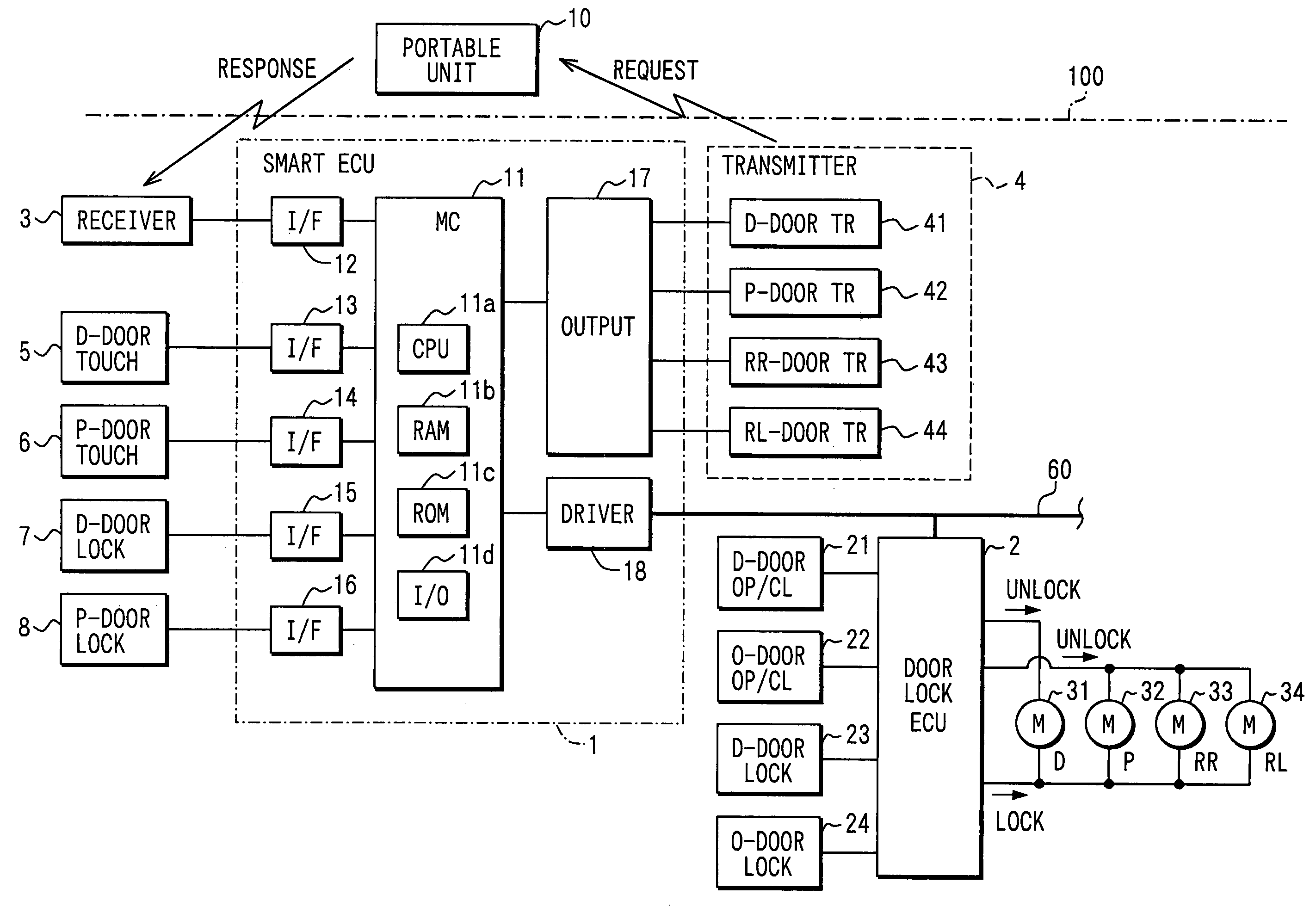
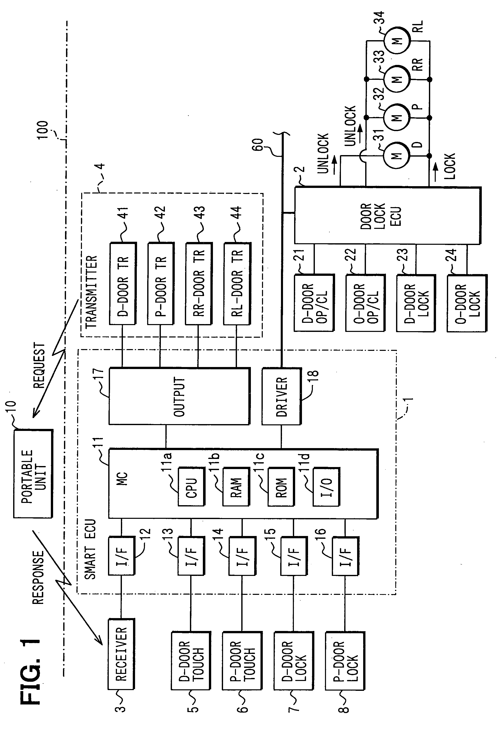
[0044] Referring to FIG. 1, a smart entry system mainly includes a portable unit 10 carried by a user such as a driver or the like, a smart ECU 1, a door lock ECU 2, a receiver 3 and a transmitter 4, which are mounted on a vehicle 100. The system also includes a portable unit 10 carried by a user such as a driver or the like. The receiver 3 is mounted at Side a vehicle compartment to receive electric waves from the portable unit 10. The transmitter 4 is mounted outside the vehicle compartment for transmitting a request signal from the vehicle 100 to the portable unit 10.

[0045] The smart ECU 1 is connected to a D-door touch sensor 5 which is contained in a door handle of the door at the driver's seat (D-seat) to detect a person touch when a user touches the door handle and output a detection signal to a smart ECU 1, a P-door touch sensor 6 which is contained in a door handle of the door at the assistant driver's (passenger') seat (P-seat) to detect a person touch when the user touch...

second embodiment

[0079] The second embodiment is similar to the first embodiment. It is however different in the following points.

(1) When the D-door 51 is opened by the time when T2 elapses after the D-door 51 is first unlocked from the unlock standby state, all the doors 51 to 54 are unlocked.

[0080] (2) When the D-door 51 is not opened even when T2 elapses after the D-door 51 is first unlocked from the unlock standby state, the other three doors 52 to 54 are kept locked.

[0081]FIG. 5 shows smart door lock control processing executed by the microcomputer 11 in this embodiment in order to implement the above (1) and (2). In this smart door lock control processing, the processing of each of S110 to S170 and the processing of S230 are the same as the smart door lock control processing of the first embodiment shown in FIG. 4.

[0082] The processing of each of S171, S173, S175, S177 and S179 is carried out after the processing of S170. That is, the processing of each of S171 to S179 is carried out in ...

third embodiment

[0088] The third embodiment is also similar to the first embodiment, but different from the first embodiment in the following points. That is, when the D-door touch sensor 5 is touched under the unlock standby state, the operation state of the D-door lock switch 7 is checked. Only the D-door 51 is unlocked when the D-door lock switch 7 is operated or all the doors 51 to 54 are unlocked when the D-door lock switch 7 is not operated.

[0089] That is, when the user wants to unlock only the D-door 51, the user may touch the D-door touch sensor 5 while operating the D-door lock switch 7. On the other hand, when the user wants to unlock the doors 51 to 54, the user may merely touch the D-door touch sensor 5.

[0090]FIG. 6 shows the smart door lock control processing executed by the microcomputer 11 of this embodiment in order to implement the above operation. As shown in FIG. 6, S110 to S160 are similar to the processing in the first embodiment shown in FIG. 4. The processing of each of S16...


PUM


Abstract

A smart entry system for a vehicle includes a transmitter on a vehicle and a portable unit carried by a user. The transmitter transmits a request signal which defines a user detection area to detect whether the portable unit transmits a response signal to indicate the user. When the user enters the detection area while all the doors are locked, an unlock standby state is set. When the user touches a touch sensor of a driver-seat side door under the unlock standby state, only the driver-seat side door is first unlocked. The other doors are kept locked if the user opens the D-door by the time when T2 seconds elapse. On the other hand, all the doors are unlocked when T2 elapses while the driver-seat side door is not opened.

Description

CROSS REFERENCE TO RELATED APPLICATION [0001] This application is related to and incorporates herein by reference Japanese Patent Application No. 2004-142752 filed on May 12, 2004. FIELD OF THE INVENTION [0002] The present invention relates to control for locking of and unlocking of doors of a vehicle, and particularly to a smart entry system for carrying out locking / unlocking control of doors of a vehicle without at Serting a key into a key cylinder of a vehicle nor operating a switch provided in the key. BACKGROUND OF THE INVENTION [0003] In a conventional keyless entry system, each actuator of a door lock mechanism of a vehicle is operated by a wireless remote control unit so that the doors of the vehicle can be locked / unlocked at a place remote from the vehicle. According to this keyless entry system, it is general that plural switches are provided on a transmitter for wireless operation at Such a manner that each operating switch has its own function. For example, all the doors...

Claims


Application Information

Patent Timeline
IPC IPC(8): E05B49/00B60R25/01B60R25/24G06F7/04
CPCB60R25/246B60R25/2036
Inventor KUMAZAKI, TAKESHIYAGYU, HIROSHI
Owner DENSO CORP
Why Eureka
Try Eureka