Precision-controllable synchronous error measurement system for multiple high-speed cameras

A high-speed camera, synchronization error technology, applied in the parts of TV systems, color TV parts, TV and other directions, can solve the problems of fixed synchronization error accuracy, only reaching ms level, unable to achieve various error accuracy, etc. Achieve the effect of easy synchronization error, accurate calculation of error value, and simple error measurement method

Active Publication Date: 2020-12-29
HEFEI JUNDA HI TECH INFORMATION TECH
View PDF6 Cites 2 Cited by
  • Summary
  • Abstract
  • Description
  • Claims
  • Application Information

AI Technical Summary

Problems solved by technology

[0003] At present, when multiple high-speed cameras are used for synchronous shooting, it is necessary to measure the synchronization error for synchronization calibration. In the prior art, the synchronization error of multiple high-speed cameras is obtained by judging the time stamp and frame interval of the image, but judging The synchronization error accuracy of high-speed cameras is fixed and can only reach the ms level, which cannot meet the various error accuracy requirements required by most customers to adapt to different usage scenarios

Method used


Image

  • Precision-controllable synchronous error measurement system for multiple high-speed cameras
  • Precision-controllable synchronous error measurement system for multiple high-speed cameras
  • Precision-controllable synchronous error measurement system for multiple high-speed cameras

Examples


Embodiment Construction

[0026] The specific implementation of the present invention will be described in detail below in conjunction with the accompanying drawings. It should be noted that these specific descriptions are only for those of ordinary skill in the art to understand the present invention more easily and clearly, rather than limiting interpretation of the present invention.

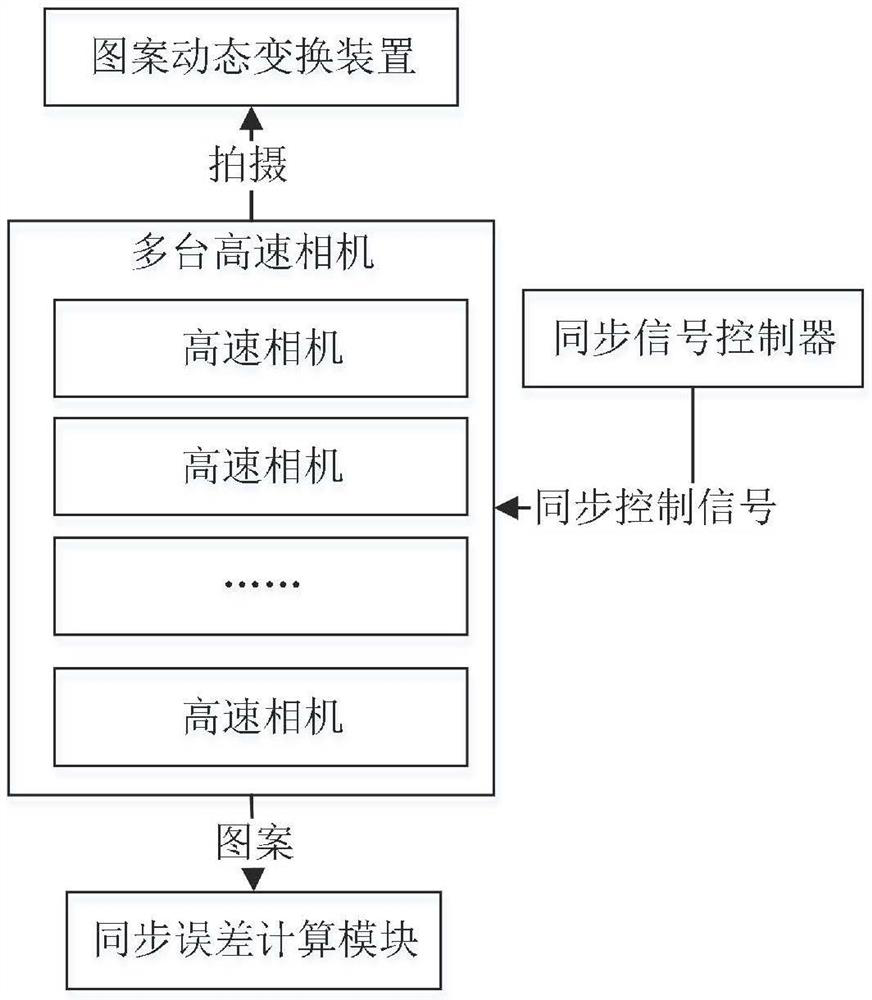
[0027] see figure 1 , the embodiment of the present invention provides a precision controllable multiple high-speed camera synchronization error measurement system, including:

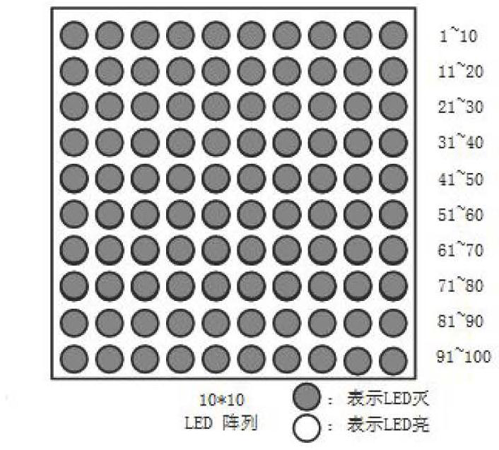
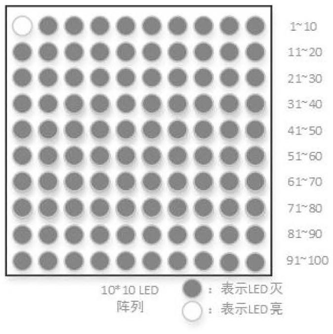
[0028] The pattern dynamic change device is based on the pulse signal sent by the FPGA to trigger the pattern to change according to the preset time interval and the preset change order. It can be understood that the pattern switched and displayed within the preset period cannot be repeated multiple times, so as to distinguish and identify;

[0029] Synchronous signal controller connected with multiple cameras;

[0030] Multiple high-speed ca...


PUM


Abstract

The invention discloses a precision-controllable synchronous error measurement system for multi-high-speed-cameras, and the system comprises a pattern dynamic conversion device which triggers a pattern to be converted according to a preset time interval and a preset conversion sequence based on a pulse signal transmitted by an FPGA, wherein the preset time interval is determined according to the measurement error precision requirement; a plurality of high-speed cameras which are used for shooting the current pattern of the pattern dynamic conversion device based on the synchronous control signal; and a synchronization error calculation module which is used for obtaining synchronization signal time errors among the plurality of cameras according to the serial number difference values of thepatterns shot by the plurality of high-speed cameras. According to the invention, synchronization error calculation for different measurement error precision requirements is realized, the measurementerror precision control method is convenient to realize, and the synchronization error calculation method is simple.

Description

technical field [0001] The invention relates to the technical field of signal synchronization control, in particular to a synchronization error measurement system for multiple high-speed cameras with controllable precision. Background technique [0002] At present, the frame rate of high-speed cameras can reach up to 1 million frames, and they are widely used in the fields of gunpowder blasting analysis, ballistic analysis, high-resolution high-speed microscope imaging, automobile crash tests, fast fluid observation, etc. Sometimes it is necessary to use multiple high-speed cameras to monitor During the test, observe and observe the changes of the test in a short period of time. [0003] At present, when multiple high-speed cameras are used for synchronous shooting, it is necessary to measure the synchronization error for synchronization calibration. In the prior art, the synchronization error of multiple high-speed cameras is obtained by judging the time stamp and frame int...

Claims


Application Information

Patent Timeline
Patent Type & Authority Applications(China)
IPC IPC(8): H04N17/00H04N5/04
CPCH04N17/002H04N5/04
Inventor 彭超卢小银陈浩雷秀军严德斌金一
Owner HEFEI JUNDA HI TECH INFORMATION TECH
Why Eureka
Try Eureka