Space positioning error measuring device and measuring method thereof

A technology of error measurement and spatial positioning, which is applied in the field of robotics, can solve the problems of inapplicable robot in-position error real-time measurement, positioning device error measurement, and large positioning error size, etc., to achieve simple structure, high precision, and simple error measurement method Effect

Active Publication Date: 2019-12-13
YIBIN VOCATIONAL & TECH COLLEGE
View PDF13 Cites 2 Cited by
  • Summary
  • Abstract
  • Description
  • Claims
  • Application Information

AI Technical Summary

Problems solved by technology

[0005] The technical problem to be solved by the present invention is that the existing positioning error is not only large in size and high in cost, but also not suitable for real-time measurement of robot positioning error. The purpose is to provide a space positioning error measurement device and its measurement method to solve Positioning device error measurement problem

Method used


Image

  • Space positioning error measuring device and measuring method thereof
  • Space positioning error measuring device and measuring method thereof
  • Space positioning error measuring device and measuring method thereof

Examples


Embodiment 1

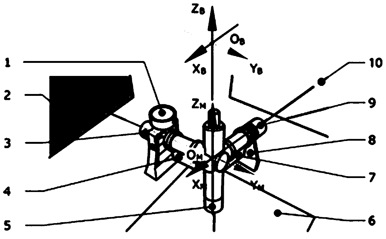
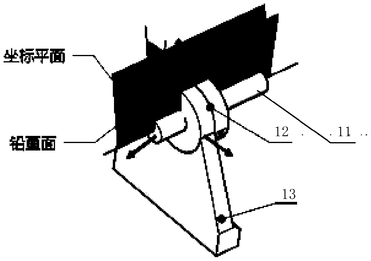
[0040] Such as Figure 1-2 As shown, the spatial positioning error measurement device and its measurement method include X rods, Y rods, Z rods, X rods, Y rods, X rods, Y rods, The Z rods are respectively equipped with high-precision laser ranging sensors for measuring the distance from the origin of the coordinate system to the bottom measurement reference surface 6, the left measurement reference surface 2, and the rear measurement reference surface 10, wherein the bottom measurement reference surface 6 is a horizontal plane , the left measurement reference surface 2 and the rear measurement reference surface 10 are two vertical surfaces perpendicular to each other and perpendicular to the bottom measurement reference surface;

[0041] The X-axis horizontal inclination sensor 7 and the Y-axis horizontal inclination sensor 4 are respectively connected to the X-axis horizontal inclination angle sensor 4 for measuring the horizontal inclination angle of the x and y coordinate a...

Embodiment 2

[0048] The measuring method of space positioning error measuring device, on the basis of embodiment 1, comprises the following steps:

[0049] (1) The transformation relationship between the measurement coordinate system {M} and the world coordinate system {W} is expressed as:

[0050]

[0051] Among them, T x (x M ), T y (y M ), T z (z M ) are respectively the homogeneous matrix of {W} to {M} moving transformation, P z (ψ), R y″ (θ) are the homogeneous matrices of {M} successively rotating and transforming around the z axis, x' axis and y" axis;

[0052]

[0053]

[0054]

[0055] (2) Obtain the angle ψ that the measurement coordinate system {M} rotates around the z-axis through the magnetic field direction sensor 1, that is, ∠bO M b';

[0056] (3) Obtain the angle that the measurement coordinate system {M} rotates around the x' axis through the Y-axis horizontal inclination sensor 4 That is, ∠b″O M b';

[0057] (4) The angle α between the zx coordi...

Embodiment 3

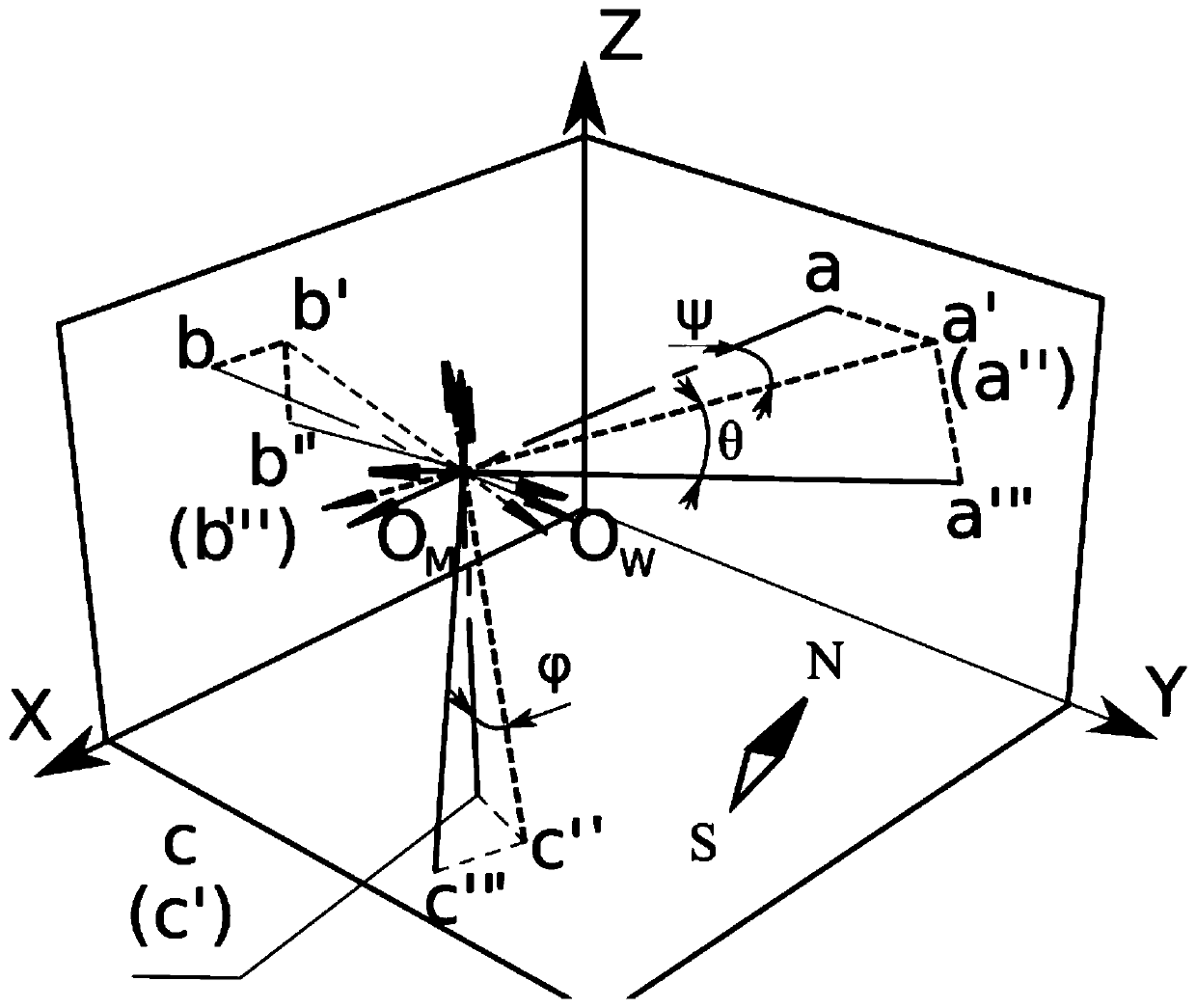
[0065] On the basis of Embodiment 2, under ideal conditions, the x, y, z coordinate axes of the measurement coordinate system {M} are orthogonal to the zy, zx, xy planes of the reference world coordinate system and three points a, b, and c respectively. Due to the positioning error of the robot base on the secondary positioning device, the measuring device deflects following the robot base, and the result of the deflection is expressed in Euler angles: the measurement coordinate system rotates around the z-axis by ψ, and around the x-axis Rotate θ around the y-axis to get the final state. The x, y, and z coordinate axes of the final measurement coordinate system {M} are orthogonal to the zy, zx, and xy planes of the reference world coordinate system and the three points a", b", and c". The measurement coordinate system {M} is relative to The Euler rotation representation of the world coordinate system {W}, that is, the formula (1);

[0066] image 3 In the rotation transfor...


PUM


Abstract

The invention discloses a space positioning error measuring device and a measuring method thereof. A magnetic field direction sensor above a y axle can measure a turning angle of a measuring coordinate system {M} in the horizontal plane; and a coordinate axle vertical dip angle sensor mounted on an x axle is used for measuring an included angle of a zx coordinate plane and the vertical plane in aplane perpendicular to the x axle. Through these measuring parameters, the position and the direction of the measuring coordinate system relative to a world coordinate system represented by a measuring reference surface can be determined, and error magnitudes of the position and the direction with correct position and direction can be determined. The device is simple in measuring method and high in measuring precision, full-automatic in measuring process and suitable for mobile robot base space positioning error measurement.

Description

technical field [0001] The invention relates to the field of robots, in particular to a space positioning error measuring device and a measuring method thereof. Background technique [0002] When the mobile industrial robot enters the station to carry out operations, due to the manufacturing, assembly, wear and other reasons of the positioning device, there is a slight error between the actual position and orientation (hereinafter referred to as the pose) and the ideal correct position and orientation, which will affect the industrial robot. Therefore, it is necessary to measure this error in order to compensate and correct the robot pose. In objective practical use, the measuring device used for the positioning error is required to have high measurement accuracy, timely and fast measurement, and small size of the measuring instrument. [0003] At present, the method of robot pose measurement uses laser tracker measurement, theodolite measurement, three-coordinate measuring...

Claims


Application Information

Patent Timeline
Patent Type & Authority Applications(China)
IPC IPC(8): B25J19/00
CPCB25J19/0095
Inventor 宋宁樊小蒲曾欣程艳奎郭容刘咸超
Owner YIBIN VOCATIONAL & TECH COLLEGE
Why Eureka
Try Eureka