
Interlayer alignment visual monitoring method

A technology with the same position in the middle layer, applied in the direction of electrical components, electrical components, etc., can solve problems such as short-circuit scrapping, cumulative deviation exceeding the standard, and unstable punching accuracy of the substrate, so as to save costs and avoid waste of manpower and material resources.

Inactive Publication Date: 2021-01-01
YIXING SILICON VALLEY ELECTRONICS TECH
View PDF16 Cites 0 Cited by
  • Summary
  • Abstract
  • Description
  • Claims
  • Application Information

AI Technical Summary

Problems solved by technology

However, in the production process, there will be many factors that cause the deviation between the core board and the core board, such as punching deviation, substrate punching accuracy instability, substrate expansion and shrinkage mismatch, and pressing slide plates, etc.
Even if the deviation of each layer is within the qualified range, as the number of layers increases, the cumulative deviation may exceed the standard, which will lead to short circuit scrapping
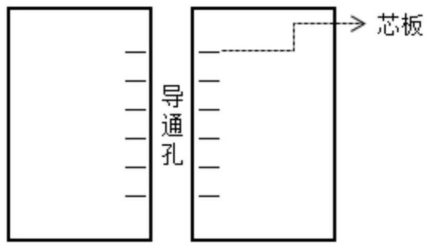
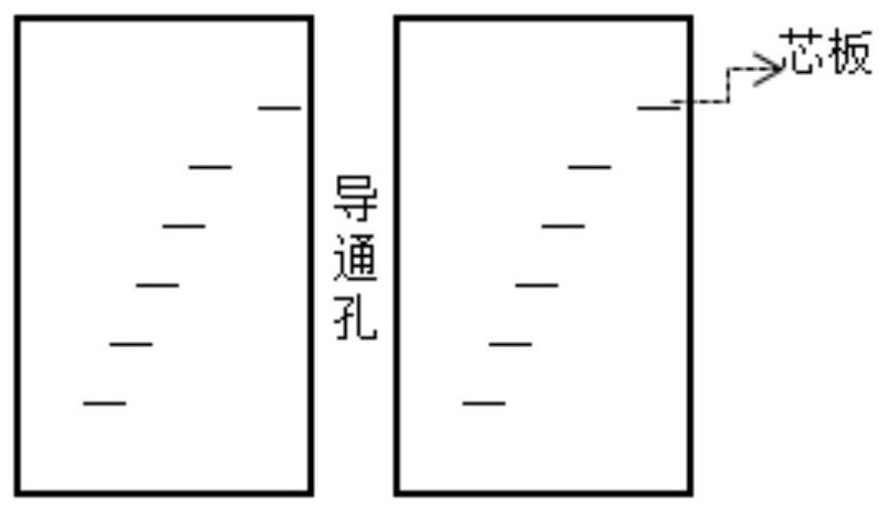
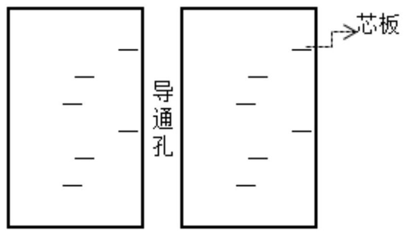
One method of judging interlayer alignment is slice analysis (eg figure 1 , figure 2 , image 3 ), but this will cause unnecessary waste. In order to reduce layer deviation, it is necessary to explore a method of alignment monitoring to make the alignment between layers more accurate

Method used


Image

  • Interlayer alignment visual monitoring method
  • Interlayer alignment visual monitoring method
  • Interlayer alignment visual monitoring method

Examples


Embodiment 1

[0032] A 22-layer board contains 10 core boards. Each core board is double-sided. The first core board is numbered 2 / 3, the second core board is numbered 3 / 4, and so on. Such as Figure 9 As shown, a concentric circle is respectively set at the same position A and B on the four corners of each core board, wherein the diameter of each layer of concentric circles at position A increases with the order of the core board in equal increments, and the diameter of each layer of concentric circles at position B diameter by Figure 7 Way cross settings:

[0033] The diameter of the concentric circles of the first core plate is the smallest, which is a;

[0034] The core board in the middle layer is set as the second largest concentric circle b (the number of core boards is an even number, and there are 2 in the middle layer, take the one with the larger code);

[0035] The last layer of core board is set as the third largest concentric circle c;

[0036] The first core board betwee...

Embodiment 2

[0045] A 20-layer board, which contains 9 core boards, each core board is double-sided, the first core board is numbered 2 / 3, the second core board is numbered 3 / 4, and so on. Such as Figure 9 As shown, a concentric circle is respectively set at the same position A and B on the four corners of each core board, wherein the diameter of each layer of concentric circles at position A increases with the order of the core board in equal increments, and the diameter of each layer of concentric circles at position B diameter by Figure 8 Way cross settings:

[0046] The diameter of the concentric circles of the first core plate is the smallest, which is a;

[0047] The core board in the middle layer is set as the second largest concentric circle b (the number of core boards is an even number, and there are 2 in the middle layer, take the one with the larger code); the last layer of core board is set as the third largest concentric circle c;

[0048] The first core board between th...


PUM


Abstract

The invention discloses an interlayer alignment visual monitoring method, and the method monitors the interlayer alignment degree by designing concentric circles with different diameters on each layer, can monitor the interlayer alignment in real time in the production process, discover a layer deviation plate in time and identify and pick out a layer deviation scrapped plate in advance, avoids the waste of manpower and material resources in the subsequent process, and effectively saves the cost.

Description

technical field [0001] The invention relates to the technical field of multilayer circuit board processing, in particular to a visual monitoring method for interlayer alignment. Background technique [0002] PCB multilayer circuit board is composed of multiple core boards, each core board is double-sided printed circuit pattern, PP is added between the core boards to form a conducting circuit through pressing, drilling, electroplating and other processes, so each core board is required The core board must be accurately aligned. With the development of global electronic information product setup and manufacturing mainly towards high-frequency, high-speed, high-level, and high-density layouts, the requirements for alignment between layers of PCB multilayer circuit boards are becoming more and more stringent. However, in the production process, there will be many factors that cause the deviation between the core board and the core board, such as punching deviation, unstable pu...

Claims


Application Information

Patent Timeline
IPC IPC(8): H05K13/08
CPCH05K13/083
Inventor 姚育松位珍光
Owner YIXING SILICON VALLEY ELECTRONICS TECH
Features
  • Generate Ideas
  • Intellectual Property
  • Life Sciences
  • Materials
  • Tech Scout
  • Unparalleled Data Quality
  • Higher Quality Content
  • 60% Fewer Hallucinations
Learn More