Self-ligating bracket opening and closing lock device

A technology of self-locking brackets and switch locks, which is applied in the direction of brackets and arch wires, which can solve the problems of inconvenient use, poor practicability, wire aiming and snap-in for doctors, etc., and achieve the effect of convenient use and strong practicability

Pending Publication Date: 2021-01-05
梁甲兴
View PDF1 Cites 1 Cited by
  • Summary
  • Abstract
  • Description
  • Claims
  • Application Information

AI Technical Summary

Problems solved by technology

However, both the steel wire and the groove are extremely small structural parts. In the actual operation process, even if the field of view is not blocked, it is difficult for the groove 36 at the end of the extension rod to accurately align and engage the steel wire. Inconvenient for doctors to use and poor in practicability

Method used


Image

  • Self-ligating bracket opening and closing lock device
  • Self-ligating bracket opening and closing lock device
  • Self-ligating bracket opening and closing lock device

Examples


Embodiment 1

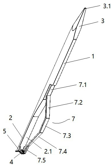
[0021] refer to Figure 1 to Figure 3 , the self-locking bracket switch locker of the present invention includes a cylindrical base 1, one end of the base 1 is provided with a relying part 2 for relying on the self-locking bracket, and the relying part can be an extension of the base , it can also be a clamp arm connected to the base body with a dependent function. In this embodiment, it is illustrated by taking the relying part 2 as an extension part of the base as an example. The other end of the base body 1 is provided with an opening portion 3 for opening the cover plate 4.1.

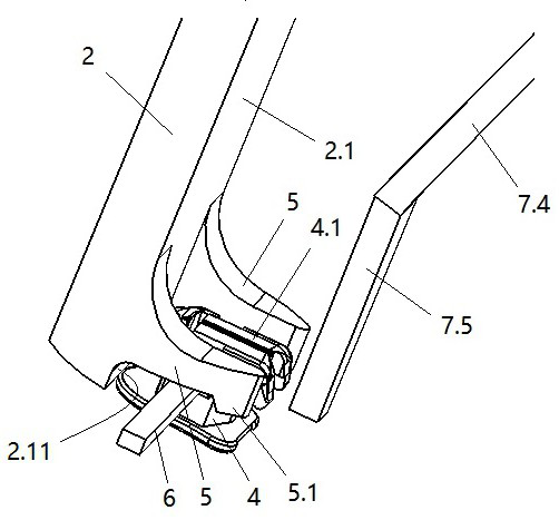
[0022] The resting part 2 includes a resting plane 2.1 arranged on the base body 1, and the resting plane 2.1 is used for stable contact with the side of the self-locking bracket 4.

[0023] A presser foot 5 for pressing the arch wire is provided on the relying portion 2, and the presser foot 5 is installed on a side of the relying portion facing the clamp arm 7, which we call a relying plane 2.1....

Embodiment 2

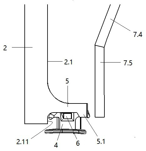
[0029] refer to Figure 4 and Figure 5 , the self-locking bracket switch locker of the present invention includes a cylindrical base 1, one end of the base 1 is provided with a relying part 2 for relying on the self-locking bracket, and the relying part can be an extension of the base , it can also be a clamp arm connected to the base body with a dependent function. In this embodiment, a clip arm with a relying function is set on the base of the relying part 2 as an example for drawing illustration. The other end of the base body 1 is provided with an opening portion 3 for opening the cover plate 4.1.

[0030] The resting part 2 includes a resting plane 2.1 arranged on the base body 1, and the resting plane 2.1 is used for stable contact with the side of the self-locking bracket 4.

[0031]A presser foot 5 for pressing the arch wire is provided on the relying portion 2, and the presser foot 5 is installed on a side of the relying portion facing the clamp arm 7, which we ca...


PUM


Abstract

The invention relates to a self-ligating bracket opening and closing lock device which comprises a base body. One end of the base body is provided with a leaning part used for leaning against a self-ligating bracket, the leaning part comprises a leaning surface facing a clamping arm, the leaning part is provided with pressing feet used for pressing an arch wire, and the pressing feet are arrangedat the position, close to the tail end, of the leaning surface. The base body is further provided with the clamping arm used for pushing a cover plate, the working end of the clamping arm can be drawntowards the pressing feet, and the two or more pressing feet are located on the two sides of a working part of the clamping arm respectively. The outer end of each pressing foot is provided with a lock hook part. The clamping arm comprises a connecting part used for being connected with the base body, an arch-shaped middle part, and the working part used for pushing the cover plate. The other endof the base body is provided with an opening part, and the opening part comprises an insertion plate located at the tail end of the base body. According to the self-ligating bracket opening and closing lock device, with the leaning part on the base body as a reference, the operation of closing the self-ligating bracket cover plate can be achieved without accurate alignment and accurate operationin the use process, blind operation is achieved, use is more convenient, and higher practicability is achieved.

Description

technical field [0001] The invention relates to the technical field of dental orthodontics, in particular to a self-locking bracket switch locker. Background technique [0002] Self-ligating brackets are generally made of materials such as metal or ceramics. In orthodontic treatment, they are usually fixed on the surface of the teeth with a special adhesive to accommodate and fix the orthodontic wire and transmit the orthodontic force to the teeth. So as to achieve the effect of orthodontics. The cover plate of the self-locking bracket can usually slide back and forth on the bracket body, so as to realize self-locking and opening. Due to the small size of the self-ligating bracket, it is difficult for doctors to open and close the cover without the assistance of corresponding tools. [0003] In order to solve this problem, a Chinese patent discloses an opener for self-locking brackets. Its patent application number is 2018 2 1813442.8. Through the design of the closing par...

Claims


Application Information

Patent Timeline
Patent Type & Authority Applications(China)
IPC IPC(8): A61C7/28
CPCA61C7/287A61C7/28
Inventor 梁甲兴林全红
Owner 梁甲兴
Why Eureka
Try Eureka