A tourist locking protection device for unpowered amusement facilities
A technology for amusement facilities and protection devices, applied in the field of tourist locking protection devices, can solve the problems of insufficient speed and convenience in aligning bolt holes, low fixing strength, etc.
- Summary
- Abstract
- Description
- Claims
- Application Information
AI Technical Summary
Problems solved by technology
Method used
Image

Examples
Embodiment 1
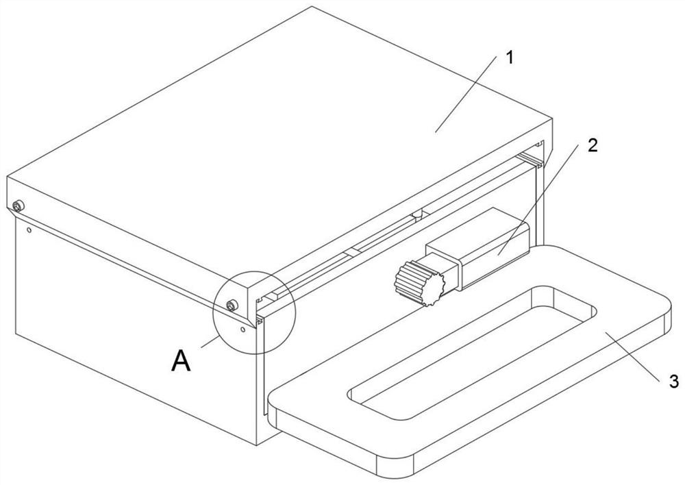
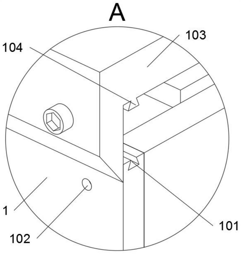
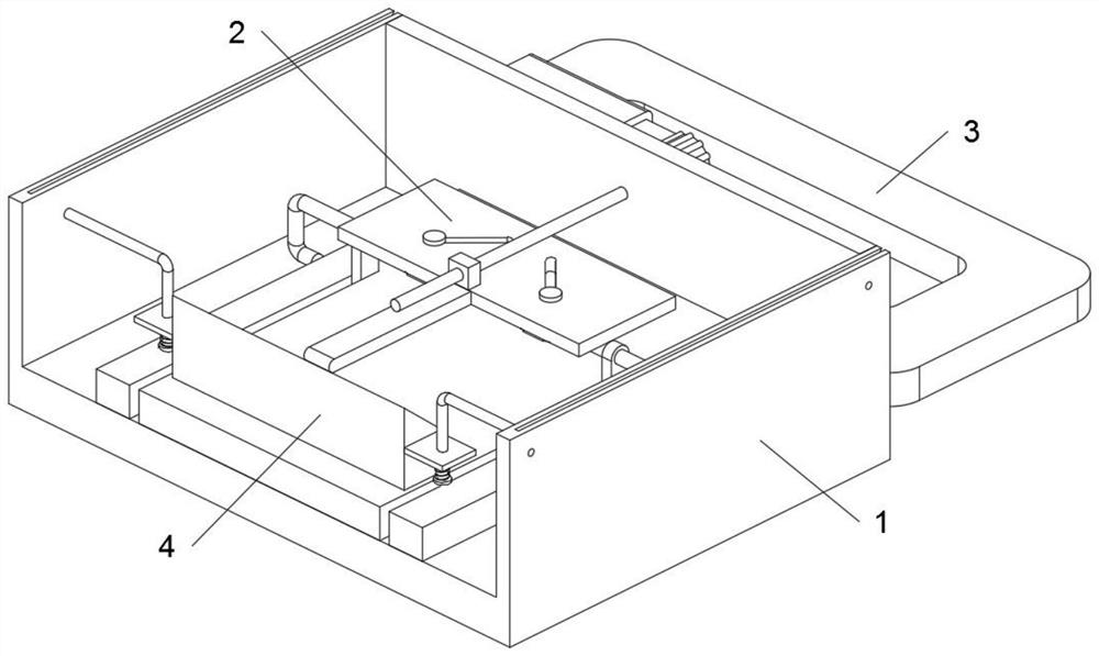
[0034] as attached figure 1 to attach Figure 9 As shown, the tourist locking protection device for non-powered amusement facilities of the present invention includes a main body seat 1; a locking structure 2 is installed in the main body seat 1, and a connector 3 is inserted into the main body seat 1, and the main body seat Auxiliary locking structure 4 is also installed in 1. Reference as Figure 5 The locking structure 2 includes a sliding rod A20201, an adjustment plate 203, a sliding hole 20301 and a threaded rod 204. There are two sliding rods A20201, and the two sliding rods A20201 are respectively welded on two locking hooks 202, and the two Each slide bar A20201 is a stepped shaft-shaped structure. The adjustment plate 203 is a rectangular plate structure, and two sliding holes 20301 are symmetrically opened on the adjustment plate 203; the sliding holes 20301 are opened in an inclined shape, and the inclination angle is 45 degrees, and two sliding rods A20201 are ...
Embodiment 2
[0038] Reference as Figure 5 , the locking structure 2 includes a connecting seat 201 and a locking hook 202, there are two connecting seats 201, and the two connecting seats 201 are welded on the main body seat 1; a lock is slidably connected to the two connecting seats 201 The hook 202 is tightened, and the locking hook 202 is a U-shaped hook structure.
[0039] Reference as Figure 5 , the connecting head 3 includes a connecting hole 301 and a locking hole A302, the connecting head 3 is provided with a connecting hole 301 for connecting with a seat belt, and the left end surface and the right end surface of the connecting head 3 are provided with a locking hole A302, And when the connecting head 3 is plugged into the main body seat 1, the locking hole A302 is aligned with the locking hook 202, so that the locking of the connecting head 3 can be realized when the threaded rod 204 is turned.
[0040] Reference as Figure 5 , the locking structure 2 also includes an adjust...
Embodiment 3
[0042] Reference as Figure 4 and Figure 5 The auxiliary locking structure 4 includes a sliding rod B401 and a locking block 402. There are two sliding rods B401, and the two sliding rods B401 are symmetrically welded in the main body seat 1, and the two sliding rods B401 are slidably connected with a lock Tight block 402; the connector 3 also includes a locking hole B303, a locking hole B303 is provided on the connector 3, and when the connector 3 is plugged into the main body seat 1, the locking hole B303 is aligned with the locking block 402, Therefore, when the locking block 402 is squeezed, the insertion and fixing of the locking hole B303 can be completed.
[0043] Reference as Figure 5 and Figure 6 , the auxiliary locking structure 4 also includes an elastic piece 403, and there are two elastic pieces 403 in total, and the two elastic pieces 403 are respectively sleeved on the two sliding rods B401, and the two elastic pieces 403 together form a locking block 402...
PUM
 Abstract
Description
Claims
Application Information
 - R&D
- Intellectual Property
- Life Sciences
- Materials
- Tech Scout
- Unparalleled Data Quality
- Higher Quality Content
- 60% Fewer Hallucinations
Browse by: Latest US Patents, China's latest patents, Technical Efficacy Thesaurus, Application Domain, Technology Topic, Popular Technical Reports.
© 2025 PatSnap. All rights reserved.Legal|Privacy policy|Modern Slavery Act Transparency Statement|Sitemap|About US| Contact US: help@patsnap.com