Novel FLVV valve, combination valve and CFLVV valve

A combined valve, a new type of technology, applied in the fields of FLVV valve, combined valve and CFLVV valve, can solve the problems of fuel escape, single spool slowness, dynamic leakage, etc., and achieve the effects of reducing fuel dynamic leakage, low transformation cost and stable performance

Pending Publication Date: 2021-01-15
AY AUTOMOTIVE TECH (JIAXING) CO LTD
View PDF0 Cites 2 Cited by
  • Summary
  • Abstract
  • Description
  • Claims
  • Application Information

AI Technical Summary

Problems solved by technology

Because the single-spool valve needs to ensure the re-opening ability of the spool, that is, under the condition of pressure, the spool can fall from the closed position in time to restore the ventilation ability, so the single-spool will be relatively slow, resulting in fuel It is easy to escape from the large air vent, causing severe dynamic leakage; the single spool is easy to close prematurely during vehicle running, blocking all the air passages, resulting in excessive pressure in the fuel tank, so it needs to be improved

Method used


Image

  • Novel FLVV valve, combination valve and CFLVV valve
  • Novel FLVV valve, combination valve and CFLVV valve
  • Novel FLVV valve, combination valve and CFLVV valve

Examples


Embodiment 1

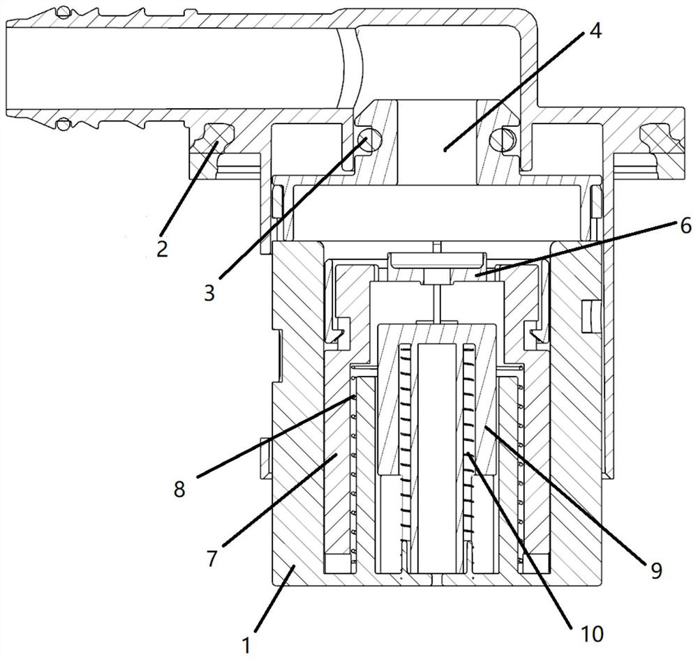
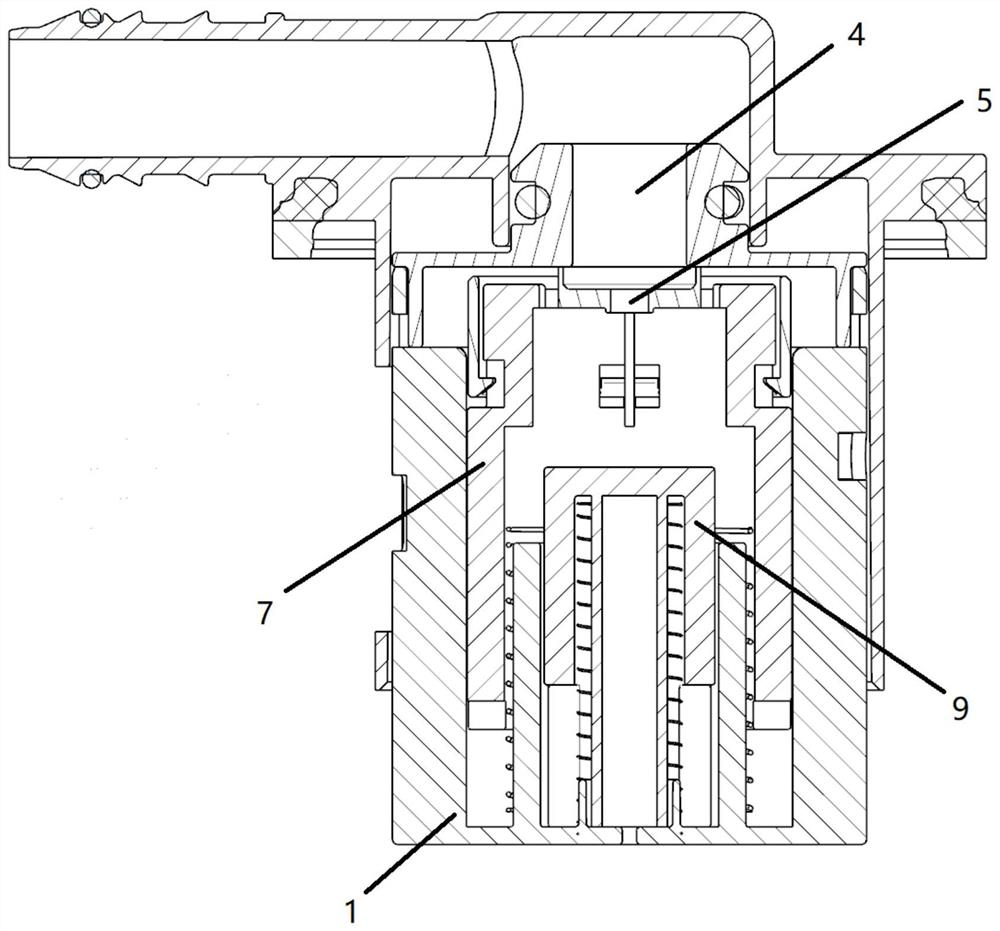
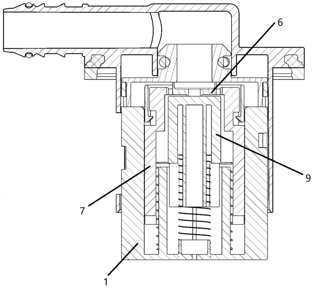
[0036] like figure 1 , figure 2 and image 3 The shown embodiment of a novel FLVV valve of the present invention includes a valve base 1 and a flange 2, and the valve base 1 is fixedly connected to the fuel tank through the flange 2, and the valve base 2 is fixedly connected to the fuel tank. An "O" seal ring 3 is also provided between the seat 1 and the flange 2, and the valve base 1 is provided with a large valve core assembly and a small valve core assembly, and the small valve core assembly is set Inside the large valve core assembly, the upper end of the valve base 1 is provided with a large vent hole 4 and a small vent hole 5 corresponding to the large valve core assembly and the small valve core assembly, and a sealing assembly 6 is provided Make a seal. The flange 2 is welded on the fuel tank for easy assembly and disassembly; the large valve core assembly includes a large float 7 and a large spring 8 used to balance the gravity of the large float 7, and the large ...

Embodiment 2

[0039] This embodiment is mainly a combined valve capable of simultaneously realizing the functions of a refueling limit valve and a reversing valve. It is applied and installed in a fuel tank, and the fluid in the fuel tank is oil and air in the fuel tank.

[0040] see Figure 4 , Figure 5 , Figure 7 and Figure 8 , The combined valve of this embodiment includes a valve base 1, a spool portion, and a pressure maintaining portion.

[0041] The valve base 1 is provided with a valve core accommodating chamber 14, and the valve base 1 is provided with a first inflow channel and a second inflow channel communicating with the valve core accommodating cavity 14 and the external space of the valve base 1, and the second The inlet of the inflow channel is higher than the inlet of the first inflow channel. The first inflow channel is mainly used for the inflow of oil and gas, and the second inflow channel is mainly used for the inflow of gas.

[0042]The upper end of the valve b...

Embodiment 3

[0068] see Figure 9 to Figure 11 In this embodiment, on the basis of the second embodiment above, several preferred implementation modes of the sealing assembly 6 are further described:

[0069] In this embodiment, the sealing assembly 6 can be specifically divided into two types of arrangement. The first is to be arranged on the top surface of the inner cavity of the spool accommodating cavity 14, and the second is to be slidably connected to the spool accommodating cavity 14. Inside.

[0070] First, the first case is explained, as follows:

[0071]The seal assembly 6 can specifically be a plurality of seals 601 respectively sleeved at the large vent hole 4 and the small vent hole 5, and each seal 601 has a seal ring extending into the spool accommodating cavity 14, and the seal rings can communicate with each other respectively. The spool accommodating cavity 14 is located in the large air hole 4 or the small air hole 5 . At this time, the large float 7 can be lifted to ...


PUM


Abstract

The invention discloses a novel FLVV valve, a combination valve and a CFLVV valve. The novel FLVV valve comprises a valve base and a flange piece, wherein the valve base is fixedly connected to a fueltank through the flange piece, an "O"-shaped sealing ring is further arranged between the valve base and the flange piece, a large valve element assembly and a small valve element assembly are arranged on the valve base, the small valve element assembly is arranged inside the large valve element assembly, a large vent hole and a small vent hole which correspond to the large valve element assemblyand the small valve element assembly are formed in the upper end of the valve base, and sealing is carried out by arranging a sealing assembly. A large valve element is sensitive and timely in closing, and can reduce dynamic leakage to the maximum extent, a small valve element is high in reopening capacity, and can maintain the pressure in an oil tank low, and meanwhile due to the fact that the corresponding vent hole of a small floater is small and located inside a large floater, dynamic leakage generated by the hole corresponding to the small floater is low.

Description

technical field [0001] The invention relates to the technical field of vehicle-mounted fuel recovery systems, in particular to a novel FLVV valve, combined valve and CFLVV valve. Background technique [0002] The existing fuel tank valve is designed with a single spool, and a moving component moves up and down to realize the opening and closing of the vent hole. In order to ensure a large air flow, the large vent hole will be opened synchronously. Because the single-spool valve needs to ensure the re-opening ability of the spool, that is, under the condition of pressure, the spool can fall from the closed position in time to restore the ventilation ability, so the single-spool will be relatively slow, resulting in fuel It is easy to escape from the large vent hole, causing serious dynamic leakage; during the running of the vehicle, the single valve core is easy to close prematurely, blocking all the vent passages, resulting in excessive pressure in the fuel tank, so it needs...

Claims


Application Information

Patent Timeline
Patent Type & Authority Applications(China)
IPC IPC(8): F16K24/04F16K27/02F16K17/04B60K15/035
CPCB60K15/03519F16K17/044F16K24/042F16K27/02
Inventor 朱晓通
Owner AY AUTOMOTIVE TECH (JIAXING) CO LTD
Why Eureka
Try Eureka