
A corrugated plate h steel group welding machine

A technology for assembling welding machines and corrugated plates, applied in welding equipment, auxiliary welding equipment, welding/cutting auxiliary equipment, etc., can solve the problems of inability to guarantee efficiency, affecting the subsequent process of corrugated plate forming, and high labor intensity of welding technicians. The effect of reducing the labor intensity of personnel, simple structure and reducing operation requirements

Active Publication Date: 2017-01-04
ZHEJIANG JINGGONG SCI & TECH
View PDF11 Cites 0 Cited by
  • Summary
  • Abstract
  • Description
  • Claims
  • Application Information

AI Technical Summary

Problems solved by technology

From the perspective of work efficiency, the work efficiency of corrugated plate assembly welding depends on the assembly time and manual welding time. Therefore, the labor intensity of welding technicians is relatively high, and stable efficiency output cannot be guaranteed. In severe cases, it will affect the follow-up of corrugated plate forming. The progress of the process

Method used


Image

  • A corrugated plate h steel group welding machine
  • A corrugated plate h steel group welding machine
  • A corrugated plate h steel group welding machine

Examples


Embodiment Construction

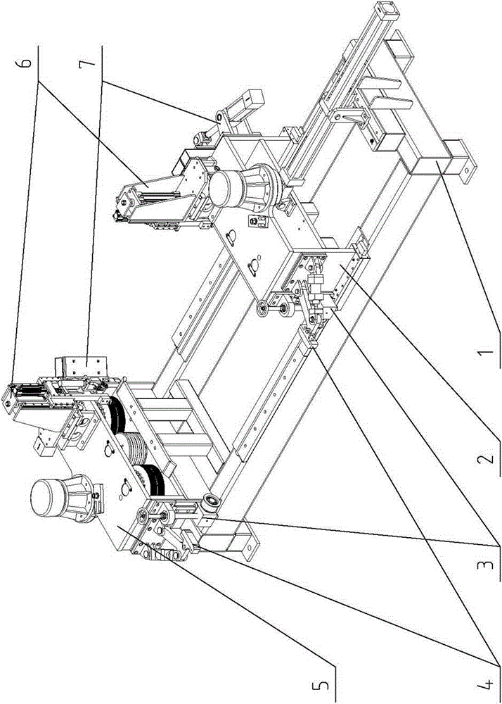
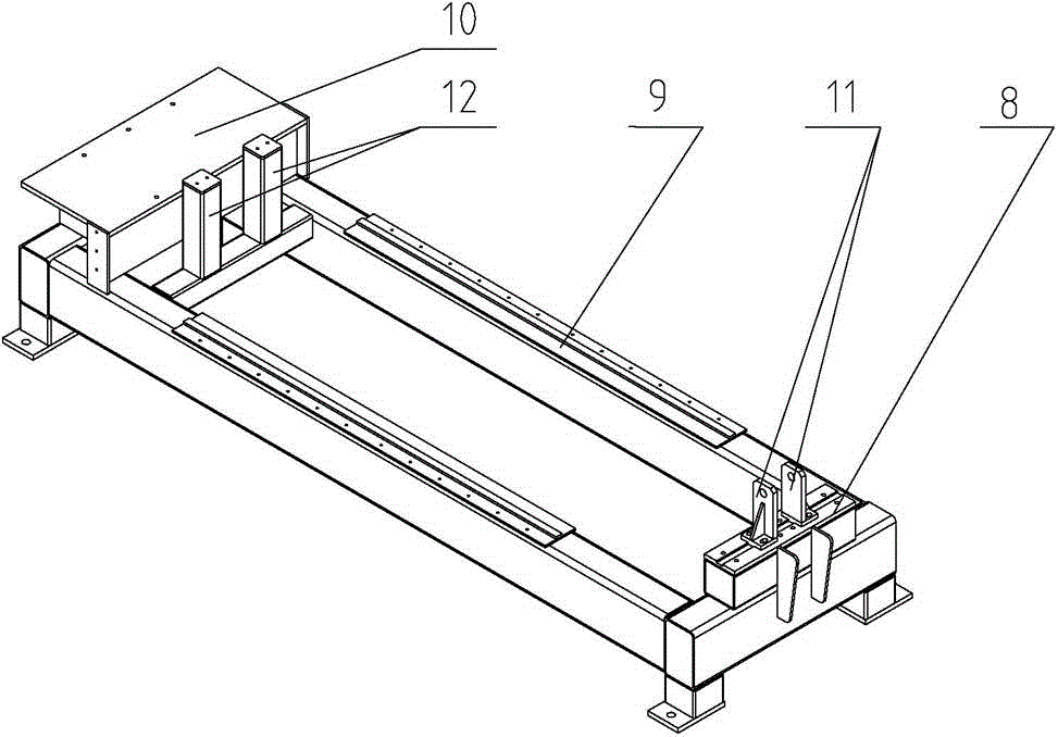
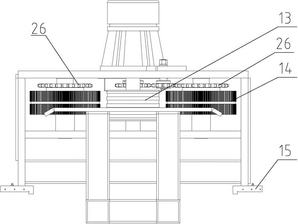
[0024] Please refer to the instruction manual figure 1 Attached Image 6 As shown, the present invention is a corrugated plate H steel group welding machine, which is assembled by the main frame 1, the movable mechanism 2, the conductive mechanism 3, the lifting mechanism 4, the fixed mechanism 5, the welding mechanism 6 and the swing mechanism 7. to make.

[0025] Wherein, one end of the main frame 1 is provided with a sliding seat 8, the other end is provided with a connecting seat 10, and a guide rail 9 is arranged in the middle; the sliding seat 8 is connected with a cylinder seat 11. The main frame 1 and the movable mechanism 2 are also provided with two equal-height uprights 12, and the four uprights 12 have the same height.

[0026] The movable mechanism 2 is arranged on the guide rail 9. The movable mechanism 2 is provided with two gear discs 14 and a magnetic roller 13; each of the gear discs 14 is provided with a sprocket 26, which are connected by a chain (not shown), ...


PUM


Abstract

The invention relates to a corrugated plate H steel set welding machine, which comprises a main machine frame, a movable mechanism, an electric conductive mechanism, a lifting mechanism, a fixation mechanism, a welding mechanism and a swing mechanism, wherein one end of the main machine frame is provided with a slide base and the other end thereof is provided with a connecting base and the middle of the main machine frame is provided with a guide rail; the slide base is connected to an air cylinder base; the movable mechanism is set on the guide rail; the fixation mechanism is set on the connecting base; the lifting mechanism and the electric conductive mechanism are respectively set at the same sides of the fixation mechanism and the movable mechanism; the swing mechanism is respectively set at the other sides of the fixation mechanism and the movable mechanism; and the welding mechanism is parallelly set above the fixation mechanism and the movable mechanism. According to the invention, the corrugated plate H steel set welding machine has both corrugated plate set function and welding function; the manual welding work is replaced; corrugated plates with variable sizes and H steels are welded as set, thus ensuring the stability and the safety, reducing the operation requirements, lowering the labor intensity of a worker, decreasing the production cost and improving the production efficiency.

Description

[0001] 【Technical Field】 [0002] The invention relates to a corrugated plate H steel forming equipment, in particular to a corrugated plate H steel group welding machine, and belongs to the technical field of building plate processing equipment. [0003] 【Background technique】 [0004] In the corrugated plate H steel forming equipment, the corrugated plate H steel assembly and welding are two key procedures. Corrugated steel H steel consists of webs and wing plates. During the forming process, the web and wing plates need to be clamped first, and then spot welding or welding is performed. On the one hand, because the state of the corrugated plate H steel assembly directly affects the result of the forming, the input, clamping and output of the assembly equipment have high stability and safety requirements. On the other hand, due to the non-synchronization of welding, it is likely to cause moon bending deformation during output, which seriously affects the production qualification r...

Claims


Application Information

Patent Timeline
Patent Type & Authority Patents(China)
IPC IPC(8): B23K37/00B23K37/04B23K37/02
CPCB23K37/00B23K37/0247B23K37/0408
Inventor 夏荣祥俞焕庆李玉刚樊幸栋
Owner ZHEJIANG JINGGONG SCI & TECH
Learn More