Supercharge Your Innovation With Domain-Expert AI Agents!

A mechanical polishing device for faucet production

A mechanical polishing and faucet technology, which is applied in the direction of grinding/polishing equipment, machine tools for surface polishing, and parts of grinding machine tools, etc., can solve problems such as grinding, and achieve the effect of reducing manpower and polishing comprehensively

Active Publication Date: 2021-10-22
FUZHOU YINSHENGWANG SANITARY WARE
View PDF8 Cites 0 Cited by
  • Summary
  • Abstract
  • Description
  • Claims
  • Application Information

AI Technical Summary

Problems solved by technology

[0005] In order to overcome the disadvantage that the current device cannot be polished in multiple directions, and thus needs to adjust the position and polish it many times, the technical problem to be solved is: to provide a mechanical polishing device for faucet production that can be polished in multiple directions

Method used


Image

  • A mechanical polishing device for faucet production
  • A mechanical polishing device for faucet production
  • A mechanical polishing device for faucet production

Examples


Embodiment 1

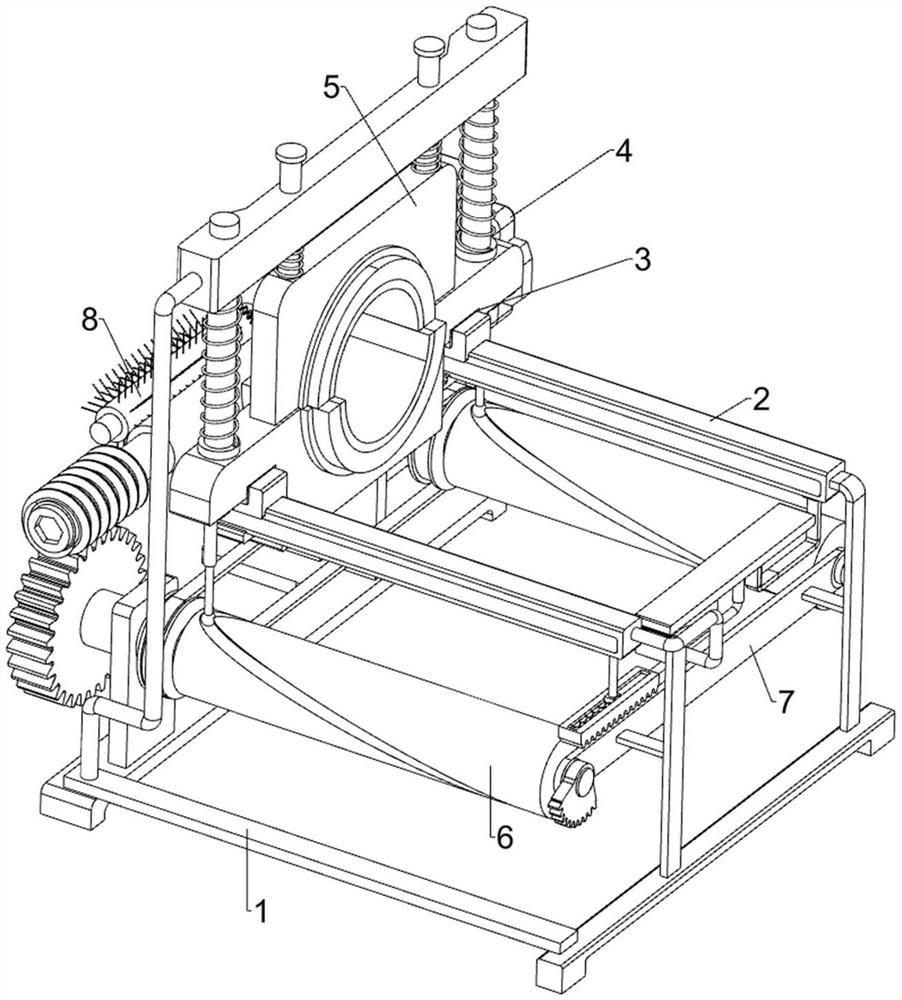
[0028] A mechanical polishing device for faucet production, such as Figure 1-4 As shown, it includes a bracket 1, a moving component 2, a placing component 3 and a polishing component 4. The upper side of the bracket 1 is provided with a moving component 2, the moving component 2 is provided with a placing component 3, and the left side of the bracket 1 is provided with a polishing component. 4.

[0029] When the faucet needs to be polished, the faucet is placed on the placing component 3, and then the polishing component 4 is started, and the polishing component 4 will polish the faucet, and at the same time, the moving component 2 can be controlled to move, thereby driving the faucet to move. Control the rotation of the faucet, and then polish the faucet in multiple directions. When the polishing of the faucet is completed, close the polishing component 4, then stop controlling the moving component 2, and then take out the polished faucet from the placement component 3.

...

Embodiment 2

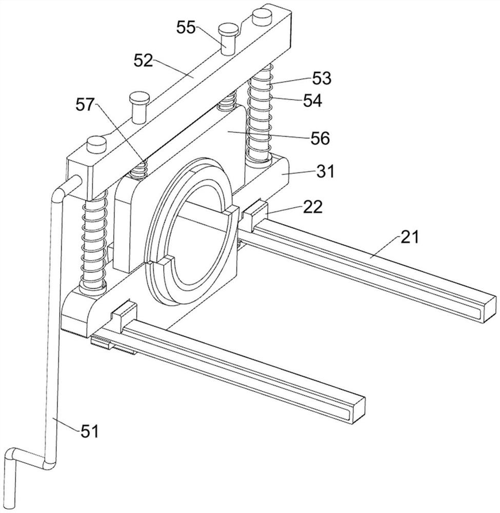
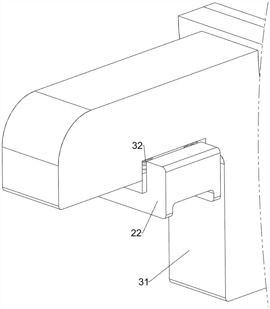
[0037] On the basis of Example 1, such as figure 2 , Figure 5 , Figure 6 and Figure 7As shown, a fixed assembly 5 is also included, and the fixed assembly 5 includes a pole 51, a mounting plate 52, a first guide rod 53, a second spring 54, a second guide rod 55, a second concave plate 56 and a third spring 57, the left front side of the bracket 1 is slidably connected with a strut 51, the rear end of the strut 51 is welded with a mounting plate 52, the front and rear sides of the mounting plate 52 are slidingly provided with a first guide rod 53, the first guide The rod 53 is connected with the first concave plate 31, the second spring 54 is connected between the first guide rod 53 and the mounting plate 52, the front and rear sides of the mounting plate 52 are all slidingly connected with the second guide rod 55, the second A second concave plate 56 is connected between the lower sides of the guide rods 55, the second concave plate 56 cooperates with the first concave ...


PUM


Abstract

The invention relates to a polishing device, in particular to a mechanical polishing device for faucet production. The technical problem to be solved by the present invention is to provide a mechanical polishing device for faucet production capable of polishing in multiple directions. A mechanical polishing device for faucet production, comprising: a bracket; a moving component installed on the bracket; a placing component installed on the moving component; a polishing component installed on the bracket. The invention has an automatic displacement assembly, which can move the telescopic rod through the cooperation of the milling groove and the roller, and then drive the faucet to move, and then does not need to manually control the faucet to move, thereby reducing the manpower consumed; The component can make the faucet rotate automatically, so that the faucet can be polished more comprehensively, and there is no need for manual control, saving time and effort.

Description

technical field [0001] The invention relates to a polishing device, in particular to a mechanical polishing device for faucet production. Background technique [0002] The faucet is a prop used in every family to control the size of the water flow. After the faucet is made, it needs to be polished. [0003] Patent authorization announcement number CN110744428A discloses a robot-based faucet polishing device, including a base, a motor is placed on the top of the base, the output shaft of the motor is fixedly connected to a connecting rod, and the end of the connecting rod far away from the motor is connected to a polishing column , the bottom of the side of the base is fixedly connected with the base block, the top of the side of the base block is provided with a first T-shaped chute, the first T-shaped chute has a first T-shaped slider, and the first T-shaped slider is far away from the first T The part of the shaped chute is fixedly connected with a mounting block, a hydra...

Claims


Application Information

Patent Timeline
Patent Type & Authority Patents(China)
IPC IPC(8): B24B29/02B24B41/06B24B41/00B08B1/04
CPCB24B29/02B24B41/06B24B41/00B08B1/12B08B1/32
Inventor 程银华
Owner FUZHOU YINSHENGWANG SANITARY WARE
Features
  • R&D
  • Intellectual Property
  • Life Sciences
  • Materials
  • Tech Scout
  • Unparalleled Data Quality
  • Higher Quality Content
  • 60% Fewer Hallucinations
Learn More