A plate automatic polishing device
An automatic polishing and plate technology, which is used in grinding drive devices, surface polishing machine tools, grinding/polishing equipment, etc., can solve the problems of uneven polishing, high labor consumption, poor fixing and clamping effect, etc., and achieve polishing efficiency. High, small footprint, easy to adjust
- Summary
- Abstract
- Description
- Claims
- Application Information
AI Technical Summary
Problems solved by technology
Method used
Image

Examples
specific Embodiment approach 1
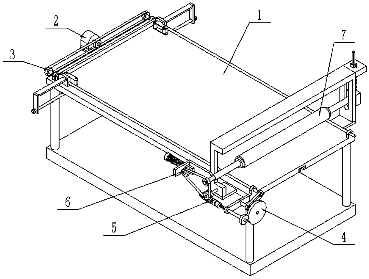
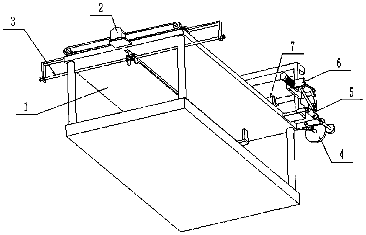
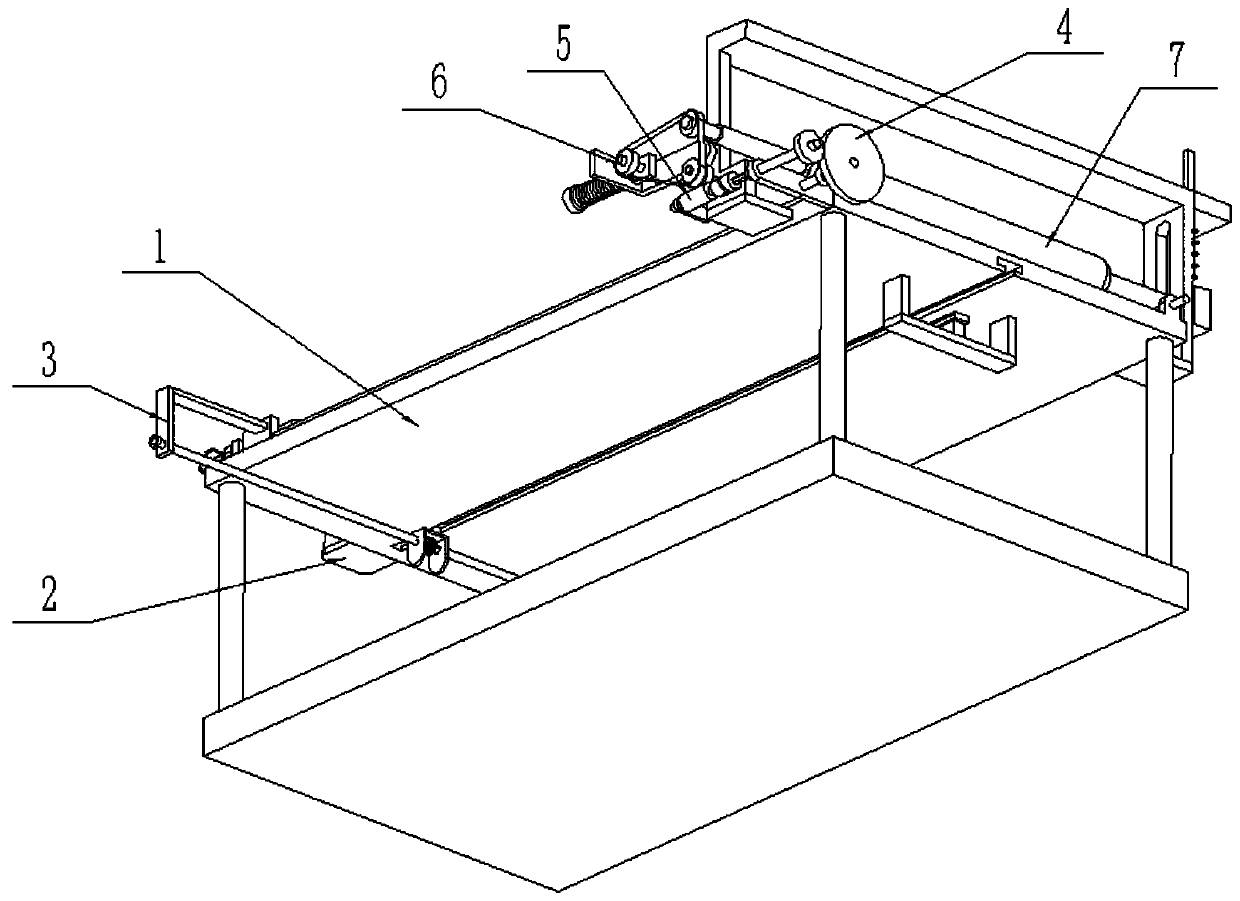
[0044] Such as Figure 1-16 As shown, a plate automatic polishing device includes a plate fixing frame 1, a drive control device 2, a clamping and pushing device 3, a transmission wheel 4, a linkage wheel 5, a tensioning wheel 6 and a polishing device 7, a plate of the present invention The automatic polishing device, when working, first transports the plate to be polished to the plate fixing frame 1 through the plate conveying device, clamps and fixes the plate to be polished by adjusting the clamping and pushing device 3, and then connects the drive control device 2 The power supply is turned on through the control switch, and after the drive control device 2 is turned on, the drive control device 2 can control the clamping and pushing device 3 to work, and the clamping and pushing device 3 drives the plate clamped on its inner side to the right on the plate fixing frame 1 Side sliding, the driving control device 2 drives the clamping and pushing device 3 to work and can dri...
specific Embodiment approach 2
[0046] Such as Figure 1-16 As shown, the plate fixing frame 1 includes an upper frame body 1-1, a support column 1-2, a lower frame body 1-3, a portal frame 1-4, a support block 1-5 and a rack 1-6; There are four supporting columns 1-2, and the upper and lower ends of the four supporting columns 1-2 are respectively fixedly connected to the four corners of the upper frame body 1-1 and the four corners of the lower frame body 1-3; A T-shaped chute with an opening on one side is provided on the bottom surface; the right end of the bottom surface of the upper frame body 1-1 is fixedly connected to the gantry 1-4, and the middle end of the gantry 1-4 is fixedly connected to the lower end of the support block 1-5. The upper end of the support block 1-5 is fixedly connected to the rack 1-6; the rack 1-6 is used to cooperate with the clamping and pushing device 3, and when the lower end of the clamping and pushing device 3 moves to the right to the position of the gantry 1-4 After ...
specific Embodiment approach 3
[0048] Such as Figure 1-16 As shown, the drive control device 2 includes a servo motor 2-1, a driving sprocket 2-2 and a motor seat 2-3; the servo motor 2-1 adopts a motor that can be purchased on the market and can carry out reciprocating motion; the servo motor 2-1 is fixedly connected to the left end of the upper frame body 1-1 through the motor base 2-3; the output shaft of the servo motor 2-1 is fixedly connected to the driving sprocket 2-2; when the drive control device 2 is in use, the servo motor When the output shaft of 2-1 rotates, it can drive the driving sprocket 2-2 to rotate around its own axis; thus, the driving sprocket 2-2 drives the clamping and pushing device 3 to work.
PUM
 Abstract
Description
Claims
Application Information