Supercharge Your Innovation With Domain-Expert AI Agents!

Polishing equipment with cleaning function

A function and equipment technology, applied in the field of polishing equipment with cleaning function, can solve the problems of low automation, low work efficiency, and high labor intensity, and achieve the effects of high automation, improved work efficiency, and reduced labor intensity

Inactive Publication Date: 2018-12-25
广州一德智能科技有限公司
View PDF4 Cites 0 Cited by
  • Summary
  • Abstract
  • Description
  • Claims
  • Application Information

AI Technical Summary

Problems solved by technology

[0002] In the processing of some metal pipe fittings, it is often necessary to polish the burrs on the inner wall of the pipe fittings. However, the traditional polishing equipment has a low degree of automation, requires too much manual operation, and has low work efficiency and high labor intensity. At the same time, the traditional It is difficult to clean the inner wall of the pipe fittings after polishing, which brings great inconvenience to the later spraying. Therefore, the traditional polishing equipment has great disadvantages and needs to be improved

Method used


Image

  • Polishing equipment with cleaning function
  • Polishing equipment with cleaning function

Examples


Embodiment Construction

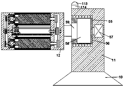
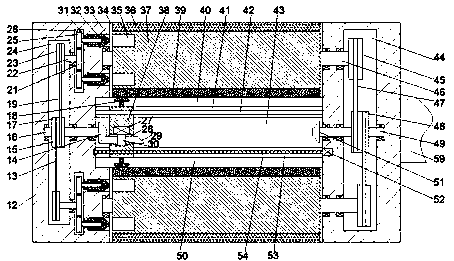
[0019] Such as Figure 1-2 As shown, a polishing device with a cleaning function of the present invention includes a base 10, a support column 11 fixedly arranged above the base 10, and a rotary sleeve 12 arranged on the left end surface of the support column 11. The sleeve 12 is provided with a first rotary cavity 34 which is symmetrical up and down and the port is facing outwards. A rotary plate 37 is rotatably provided in the first rotary cavity 34 through the first rotary shaft 46. The outer end surface of the rotary plate 37 is fixed with a Polishing strip 36, the inner end surface of the rotating plate 37 is fixed with cleaning cotton 39, the left end surface of the rotating plate 37 is symmetrically provided with a locking hole 35 with the port facing left, and the left inner wall of the first rotating cavity 34 A first sliding groove 33 opposite to the locking hole 35 is provided symmetrically in the middle and up and down, and a locking block 32 is slidably installed ...


PUM


Abstract

The invention discloses polishing equipment with a cleaning function. The polishing equipment comprises a base, a supporting column fixedly arranged on the base, and a rotating sleeve arranged on theleft side end face of the supporting column. First rotating cavities which are symmetrical in the up-down direction and are provided with outward end openings are formed in the rotating sleeve, rotating plates are rotatably arranged in the first rotating cavities through first rotating shafts, and polishing strips are fixedly arranged on the outer side end faces of the rotating plates. Cleaning cotton is fixedly arranged on the inner side end face of each rotating plate. Locking holes with leftward end openings are formed in the left side end faces of the rotating plates in an up-down symmetrical mode. First sliding grooves opposite to the locking holes are formed in the inner walls of the left sides of the first rotating cavities in an up-down symmetrical mode, locking blocks are slidablymounted in the first sliding grooves, and first spiral holes with leftward end openings are formed in the locking blocks.

Description

technical field [0001] The invention relates to the technical field of polishing, in particular to a polishing device with a cleaning function. Background technique [0002] In the processing of some metal pipe fittings, it is often necessary to polish the burrs on the inner wall of the pipe fittings. However, the traditional polishing equipment has a low degree of automation, requires too much manual operation, and has low work efficiency and high labor intensity. At the same time, the traditional It is difficult to clean the inner wall of the pipe fittings after polishing, which brings great inconvenience to the later spraying. Therefore, the traditional polishing equipment has great disadvantages and needs to be improved. Contents of the invention [0003] The technical problem to be solved by the present invention is to provide a polishing device with a cleaning function, which can solve the above-mentioned problems in the prior art. [0004] The present invention is ...

Claims


Application Information

Patent Timeline
IPC IPC(8): B24B9/04B24B29/08B24B47/12B24B47/14B08B9/047
CPCB08B9/0436B08B9/047B24B9/04B24B29/08B24B47/12B24B47/14
Inventor 韦树军
Owner 广州一德智能科技有限公司
Features
  • R&D
  • Intellectual Property
  • Life Sciences
  • Materials
  • Tech Scout
  • Unparalleled Data Quality
  • Higher Quality Content
  • 60% Fewer Hallucinations
Learn More