Supercharge Your Innovation With Domain-Expert AI Agents!

Polishing equipment with cleaning function

A function and equipment technology, applied in the field of polishing equipment with cleaning function, can solve the problems of high labor intensity, low work efficiency and low degree of automation, and achieve the effect of reducing labor intensity, improving work efficiency and high degree of automation

Inactive Publication Date: 2019-01-11
广州冠松电力科技有限公司
View PDF4 Cites 0 Cited by
  • Summary
  • Abstract
  • Description
  • Claims
  • Application Information

AI Technical Summary

Problems solved by technology

[0002] In the processing of some metal pipe fittings, it is often necessary to polish the burrs on the inner wall of the pipe fittings. However, the traditional polishing equipment has a low degree of automation, requires too much manual operation, and has low work efficiency and high labor intensity. At the same time, the traditional It is difficult to clean the inner wall of the pipe fittings after polishing, which brings great inconvenience to the later spraying. Therefore, the traditional polishing equipment has great disadvantages and needs to be improved

Method used


Image

  • Polishing equipment with cleaning function
  • Polishing equipment with cleaning function

Examples


Embodiment Construction

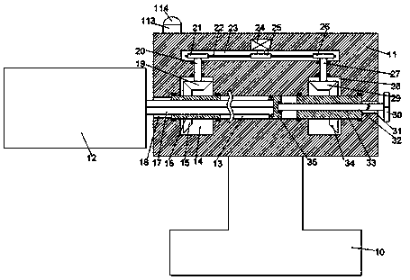
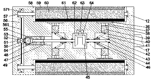
[0017] Such as Figure 1-2As shown, a polishing device with a cleaning function of the present invention includes a rotating device and a cleaning device arranged on the left side of the rotating device. The rotating device includes a chassis 11 fixedly arranged on a machine base 10. The chassis 11 is provided with a left and right extended first sliding groove 13, and the inner walls of the left and right sides of the first sliding groove 13 are respectively provided with a first connecting groove 18 and a second connecting groove 31 communicating with the outside. The upper and lower end walls of the sliding groove 13 are respectively provided with a first rotating chamber 14 and a second rotating chamber 28, and the left and right ends of the first sliding groove 13 are rotatably installed with bearings respectively penetrating through the first rotating chamber 14 and the second rotating chamber 28. The first rotating sleeve 16 and the second rotating sleeve 33 of the seco...


PUM


Abstract

The invention discloses polishing equipment with a cleaning function. The polishing equipment comprises a rotating device and a cleaning device arranged on the left side of the rotating device; the rotating device comprises a case fixedly arranged on a base; a first sliding groove extending left and right is formed in the case; a first communication groove and a second communication groove communicating with the outside are formed in the left inner wall and the right inner wall of the first sliding groove separately; a first rotary cavity and a second rotary cavity are formed in the upper endwall and the right end wall of the first sliding groove separately; a first rotary sleeve penetrating through the first rotary cavity and a second rotary sleeve penetrating through the second rotary cavity are rotationally installed at the left end and the right end of the first sliding groove separately; a first sliding block is slidably installed in the portion, between the first rotary sleeve and the second rotary sleeve, of the first sliding groove; and a first spline groove is formed in the first rotary sleeve in a horizontal penetration mode.

Description

technical field [0001] The invention relates to the technical field of polishing, in particular to a polishing device with a cleaning function. Background technique [0002] In the processing of some metal pipe fittings, it is often necessary to polish the burrs on the inner wall of the pipe fittings. However, the traditional polishing equipment has a low degree of automation, requires too much manual operation, and has low work efficiency and high labor intensity. At the same time, the traditional It is difficult to clean the inner wall of the pipe fittings after polishing, which brings great inconvenience to the later spraying. Therefore, the traditional polishing equipment has great disadvantages and needs to be improved. Contents of the invention [0003] The technical problem to be solved by the present invention is to provide a polishing device with a cleaning function, which can solve the above-mentioned problems in the prior art. [0004] The present invention is ...

Claims


Application Information

Patent Timeline
IPC IPC(8): B24B9/04B24B55/00B24B55/06B24B47/00B24B47/12B24B47/16F21V33/00F21W131/403
CPCB24B9/04B24B47/00B24B47/12B24B47/16B24B55/00B24B55/06F21V33/00F21W2131/403
Inventor 童时敏
Owner 广州冠松电力科技有限公司
Features
  • R&D
  • Intellectual Property
  • Life Sciences
  • Materials
  • Tech Scout
  • Unparalleled Data Quality
  • Higher Quality Content
  • 60% Fewer Hallucinations
Learn More