Check patentability & draft patents in minutes with Patsnap Eureka AI!

Automatic spin lock device

A lock device and automatic technology, applied in the direction of transportation and packaging, load hanging components, etc., can solve the problems of increased waiting time and unsatisfactory, and achieve the effect of fast action time

Pending Publication Date: 2021-01-22
BEIJING INST OF SPECIALIZED MACHINERY
View PDF5 Cites 0 Cited by
  • Summary
  • Abstract
  • Description
  • Claims
  • Application Information

AI Technical Summary

Problems solved by technology

However, this method requires manual operation every time, which increases the waiting time for subsequent processes, and it is far from meeting the current needs of automated production.

Method used


Image

  • Automatic spin lock device
  • Automatic spin lock device
  • Automatic spin lock device

Examples


Embodiment Construction

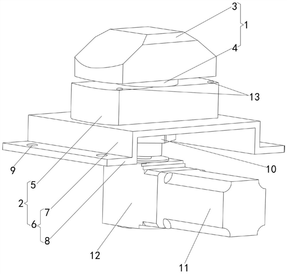
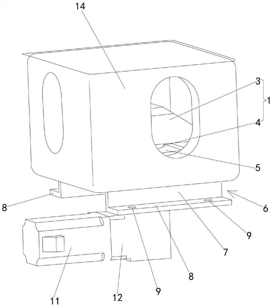
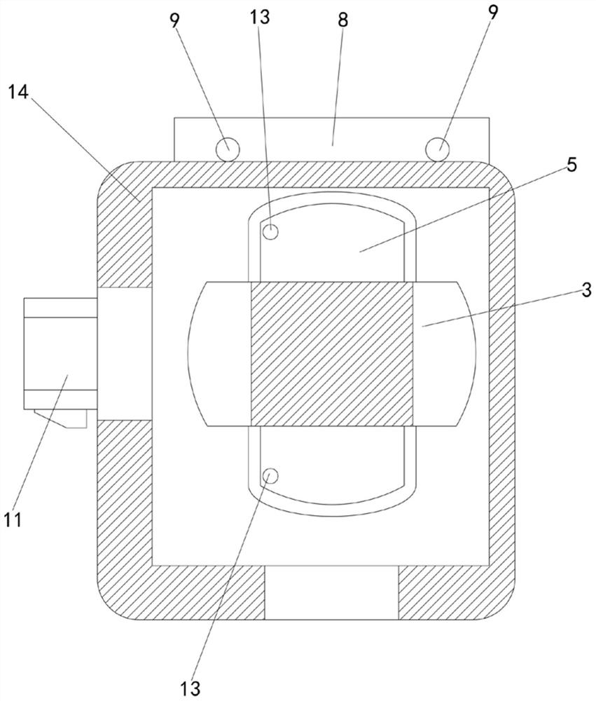
[0020] Such as figure 1 As shown, the automatic twist lock device of the present invention includes a lock head 1 and a lock body 2, the lock head 1 is connected with the lock body 2 through a threaded connection structure, and one end of the lock head 1 passes through the lock body 2 and is connected with the power mechanism. The size is such that it can extend into the inner cavity of the corner fitting, and can be clamped and fixed in the inner cavity of the corner fitting after being driven by the power mechanism to rotate at a predetermined angle.

[0021] The specific structure is: the lock head 1 includes a lock head head 3 at the upper end and a rod body 4 at the lower end of the lock head head 3. The cross-sectional size of the rod body 4 is smaller than the cross-sectional size of the lock head head 3. The lock of this embodiment The head head 3 is approximately cuboid, and its cross-sectional length is less than the lower opening length of the corner fitting but gre...


PUM


Abstract

The invention discloses an automatic spin lock device which comprises a lock head and a lock body. The lock head is connected with the lock body through a threaded connection structure, and one end ofthe lock head penetrates through the lock body and then is connected with a power mechanism. The lock head of the size can extend into an inner cavity of a corner fitting and can be clamped and fixedin an inner cavity of the corner fitting after being driven by the power mechanism to rotate by a preset angle. The threaded connection structure comprises a nut arranged on the lock body and a thread arranged on the outer surface of the lock head. The lock head penetrates through the lock body and then is connected with the nut in a threaded mode. The end, penetrating through the nut, of the lock head is connected with the power mechanism. The automatic spin lock device is ingenious in structural design, capable of being automatically locked with and separated from the corner fitting and wide in application range.

Description

technical field [0001] The invention relates to the technical field of locks, in particular to an automatic twist lock device for locking and separating corner pieces of a container. Background technique [0002] At present, most of the twistlocks and corner fittings of container spreaders are locked manually. After the docking between the twist lock and the corner fitting is completed, the rotary handle is manually turned to realize the locking and separation of the twist lock and the corner fitting. However, this method requires manual operation every time, which increases the waiting time of the subsequent process, and it is far from meeting the needs of current automated production. [0003] How to design a kind of automatic twist lock device that can solve the above technical problems is the subject of the inventor's painstaking research. Contents of the invention [0004] The object of the present invention is to provide an automatic twist lock device, which has an...

Claims


Application Information

Patent Timeline
Patent Type & Authority Applications(China)
IPC IPC(8): B66C1/10B66C13/16
CPCB66C1/101B66C13/16
Inventor 刘劭纯魏永智段三军
Owner BEIJING INST OF SPECIALIZED MACHINERY
Features
  • R&D
  • Intellectual Property
  • Life Sciences
  • Materials
  • Tech Scout
  • Unparalleled Data Quality
  • Higher Quality Content
  • 60% Fewer Hallucinations
Learn More