Load overcurrent protection circuit and load overcurrent protection method

A load overcurrent protection circuit technology, which is applied to emergency protection circuit devices, circuit devices, emergency protection devices with automatic disconnection, etc., can solve the problems of inability to set different delay shutdown times, system fault-tolerant performance degradation, and lack of flexibility And other issues

Active Publication Date: 2017-02-22
YIJIAHE TECH CO LTD
View PDF13 Cites 15 Cited by
  • Summary
  • Abstract
  • Description
  • Claims
  • Application Information

AI Technical Summary

Problems solved by technology

If the delay timer inside the chip is not used, as long as the voltage drop on the sampling resistor exceeds the reference value, the chip will quickly turn off the MOS tube, so that when the load has an overcurrent of hundreds of microseconds, the power management chip will still turn off The MOS tube is broken, which

Method used


Image

  • Load overcurrent protection circuit and load overcurrent protection method
  • Load overcurrent protection circuit and load overcurrent protection method
  • Load overcurrent protection circuit and load overcurrent protection method

Examples


Embodiment Construction

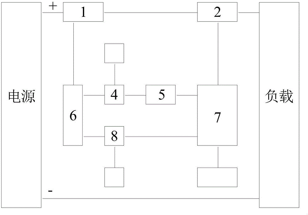
[0033] Such as figure 1 As shown, the present invention includes a load overcurrent protection function and a peak current shutdown function, figure 1 The circuit shown is connected to the positive line of the power supply. Correspondingly, the circuit can also be connected to the negative line of the power supply. The circuit provided by the present invention comprises current sampling resistor 1, electronic switch 2, amplifier 6, comparator one 4, timer 5, self-locking control circuit 7, comparator two 8, unlocking circuit 10, comparator one 4 and timer 5 constitutes a comparison delay circuit. The current sampling circuit 1 is connected to the positive pole of the power supply, the electronic switch 2, and the amplifier 6, the electronic switch 2 is connected to the load, and the self-locking control circuit 7, the amplifier 6 is connected to the comparator 1 4 and the comparator 2 8, and the comparator 1 4 is connected to the reference source 13. Timer 5 is connected, co...


PUM


Abstract

The invention provides a load overcurrent protection circuit. The load overcurrent protection circuit comprises a current sampling resistor, an amplifier, a comparator I, a timer, a self-locking control circuit and an electronic switch, wherein the current sampling resistor is connected with the electronic switch; the comparator I is connected with a reference source I; the amplifier amplifies the voltage of the current sampling resistor and transmits the voltage to the comparator I; the comparator I compares a voltage signal output by the amplifier with the reference source I; and the timer starts time delay timing if the voltage signal output by the amplifier is higher than the reference source I, the timer stops timing and the electronic switch normally switches on if the voltage signal output by the amplifier is lower than the reference source I in the time delay timing process, otherwise, the timer performs time delay timing to reach a set value, and the self-locking control circuit switches off the electronic switch and locks the off state of the electronic switch. The load overcurrent protection circuit solves the problems that the delayed time of overcurrent protection is short and an MOS tube is susceptible to burnout.

Description

technical field [0001] The invention belongs to the technical field of robot control, and in particular relates to a load overcurrent protection circuit and a load overcurrent protection method. The protection circuit of the invention also relates to a peak current shutdown circuit. Background technique [0002] The power management solutions introduced by chip manufacturers, such as TI's power management chip TPS2490 / TPS2491 and LINEARTECHNOLOGY's LT4363, both connect an electronic switch (MOS tube) and a sampling resistor in series to the positive line of the power bus, and connect a capacitor externally to the power management chip to set The delay time of the internal timer. The power management chip monitors the voltage drop on the sampling resistor and compares it with the internal reference source. When the voltage drop on the sampling resistor exceeds the reference source, the power management chip starts to adjust the gate voltage of the MOS tube. To limit the volta...

Claims


Application Information

Patent Timeline
IPC IPC(8): H02H3/093
CPCH02H3/093
Inventor 张锦程王锋林欢程敏赵伟邱显东许春山
Owner YIJIAHE TECH CO LTD
Why Eureka
Try Eureka