Magnetic source non-modulation type transmitter and control method thereof

A non-modulation, control method technology, applied in the field of geophysical exploration equipment, can solve the problems of large shallow blind area, reverse current, long turn-off delay, etc. short delay effect

Inactive Publication Date: 2015-03-11
JILIN UNIV
View PDF6 Cites 24 Cited by
  • Summary
  • Abstract
  • Description
  • Claims
  • Application Information

AI Technical Summary

Problems solved by technology

[0003] CN203786309U discloses a kind of " transient electromagnetic transmitter passive absorption circuit ", adopts TVS tube, SIDAC device to absorb the emission current in the transmitting coil when shutting off, reduces the current shutoff time, but is often applied in strong inductive magnetic source ( Coil) The turn-off delay on the load is still too long, and the falling edge of the current waveform of the turn-off delay is nonlinear, uncontrollable, and the shallow dead zone is very large
[0004] Existing aeronautical transient electromagnetic transmitters use modulated transmission technology, although the current turn-off delay and current rise time are reduced, but the transmission current waveform is modulated, the waveform is unstable, and the current ripple is large, which will cause Generate electromagnetic interference, thus affecting the detection accuracy
[0005] Zhao Haitao published "Constant Voltage Clamp High-Speed ​​Turn-Off Transient Electromagnetic Transmitter System" in the 4th issue of "Journal of Instrumentation" in 2013, P803-808, and mentioned the "constant voltage clamp circuit". After the circuit is applied, the current is turned off. The delay is short, the linearity of the current falling edge is high, and the rising speed of the current leading edge is increased, but the current reverses after being turned off, and it has oscillations, which has a relatively large impact on the secondary field and also brings new problems to the data inversion interpretation. a lot of difficulty

Method used


Image

  • Magnetic source non-modulation type transmitter and control method thereof
  • Magnetic source non-modulation type transmitter and control method thereof
  • Magnetic source non-modulation type transmitter and control method thereof

Examples


Embodiment Construction

[0034] Below in conjunction with accompanying drawing and embodiment the present invention is described in further detail:

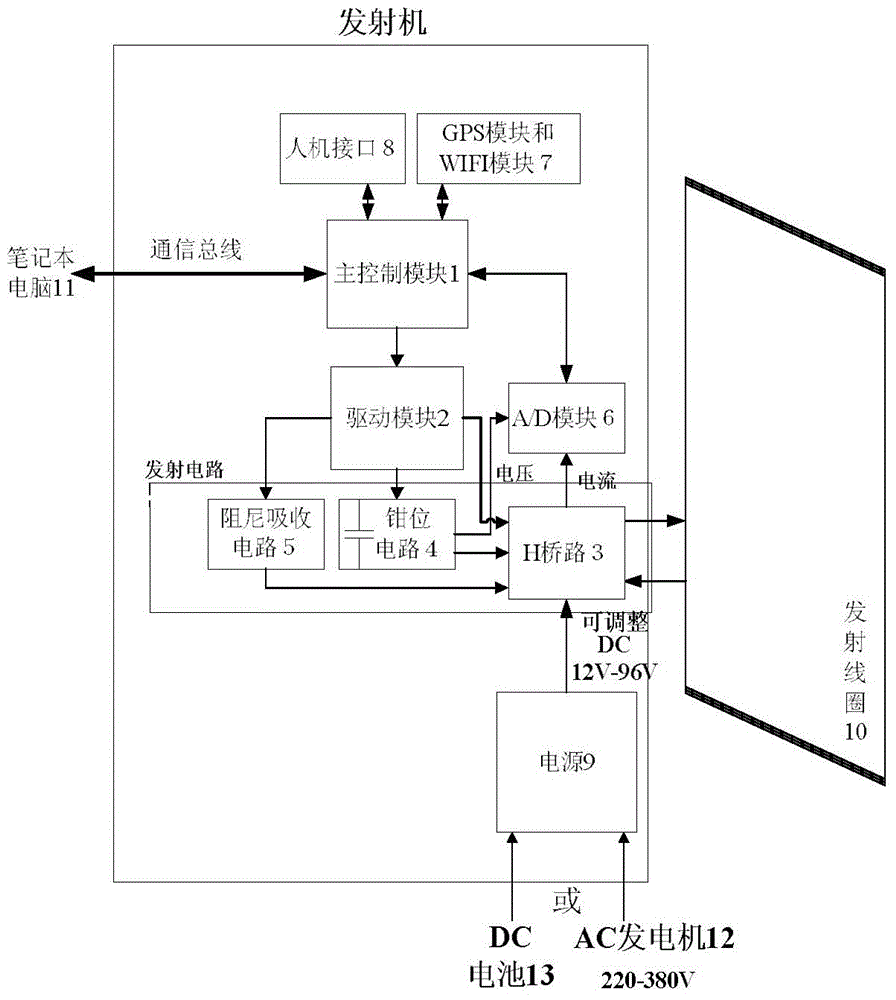
[0035] The magnetic source non-modulated transmitter is connected to the man-machine interface 8, GPS module, WIFI module 7, and notebook computer 11 respectively by the main control module 1, and the main control module 1 is connected to the power supply 9 via the A / D module 6 and the H bridge circuit 3 connection, the main control module 1 is connected to the transmitting coil 10 through the driving module 2, the clamping circuit 4 and the H bridge circuit 3, the driving module 2 is connected to the transmitting coil 10 through the damping absorption circuit 5 and the H bridge circuit 3, and the driving module 2 is connected to the H bridge circuit 3. The bridge circuit 3 is connected, and the clamping circuit 4 is connected with the A / D module 6 to form a structure.

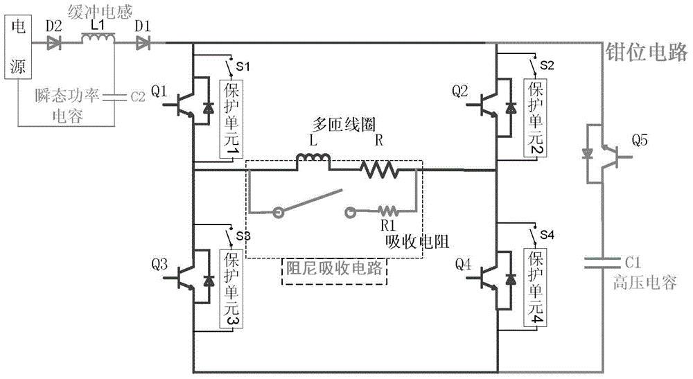
[0036] The forward power supply of the H-bridge circuit 3 begins to conduct Q1 and Q...


PUM


Abstract

The invention relates to a magnetic source non-modulation type transmitter. The magnetic source non-modulation type transmitter is formed in a way that a man-machine interface, a GPS (Global Positioning System) module, a WIFI (Wireless Fidelity) module and a notebook computer are respectively connected with a master control module, the master control module is connected with a power supply through an A/D module and an H bridge circuit, the master control module is connected with a transmitting coil through a driving module, a clamping circuit and the H bridge circuit, the driving module is connected with the transmitting coil through a damping absorbing circuit and the H bridge circuit and connected with the H bridge circuit, and the clamping circuit is connected with the A/D module. The magnetic source non-modulation type transmitter solves ringing phenomena occurring when the current is lowered below zero and plays an important role of reducing primary filed influence in shallow detection. More pure secondary field signals are obtained, the quality of transient electromagnetic data is improved, and high-quality data are provided for the processing and inversion of transient electromagnetic data, in particular, transient electromagnetic early data. The magnetic source non-modulation type transmitter is suitable for various types of transmitting coils, the transmitting current waveform is controllable, turn-off time delay is short, the current falling edge linearity is high, the transmitting current is large, and the current leading edge raising speed is accelerated.

Description

technical field [0001] The invention relates to a geophysical exploration equipment, especially a transient electromagnetic transmitting system, especially a magnetic source electromagnetic transmitter whose transmitting antenna is loaded by a strong inductive magnetic source (coil). Background technique [0002] Time-domain transient electromagnetic method (TEM) is a prospecting method with very broad application prospects in the field of geophysical exploration, and has been successfully applied to engineering exploration such as coal mines, metal mines, oil, and gas exploration. Transient electromagnetic transmitters usually use coil loads with large inductance and small resistance. Especially in special occasions such as aeronautical electromagnetic methods and downhole electromagnetic methods, the size of the coil is limited. In fact, multi-turn small coils are often used. Therefore, special requirements are put forward for the power conversion circuit of the transient ...

Claims


Application Information

Patent Timeline
Patent Type & Authority Applications(China)
IPC IPC(8): G01V3/08
Inventor 王世隆杨宇胡雪岩林君
Owner JILIN UNIV
Why Eureka
Try Eureka