
Hydraulic drill convenient to move

A hydraulic and driving wheel technology, applied in the field of hydraulic drilling, can solve the problems of increased equipment cost, mud and dust pollution, low efficiency, etc., and achieve the effects of prolonging service life, reducing impact and facilitating movement

Inactive Publication Date: 2018-12-21
WUHAN UNIV OF SCI & TECH
View PDF5 Cites 1 Cited by
  • Summary
  • Abstract
  • Description
  • Claims
  • Application Information

AI Technical Summary

Problems solved by technology

[0002] In the prior art, construction equipment, such as drilling rigs, has a short drilling stroke during the construction process. Generally, the longest common equipment is no more than 5 meters, and its efficiency is low; it will generate a lot of mud and dust pollution; when drilling intensively, It is difficult to accurately and quickly align the hole positions; the available drilling technology is single, which cannot meet the drilling construction needs of various complex strata; the drilling rig power system is single, and the construction conditions are high
[0003] In particular, the existing drilling rig equipment is highly targeted, and generally can only cope with a single terrain and the surrounding environment of the construction. It is difficult to maintain continuous and stable work when the terrain of the construction location changes, which greatly reduces the construction efficiency. In order to adapt to different terrain conditions, it is necessary to There are multiple sets of drilling rig equipment in reserve, which also increases the construction equipment cost accordingly
In addition, the drilling rig equipment is heavy and bulky, and it is extremely inconvenient to transfer when changing the construction site.

Method used


Image

  • Hydraulic drill convenient to move

Examples


Embodiment Construction

[0025] The following will clearly and completely describe the technical solutions in the embodiments of the present invention with reference to the accompanying drawings in the embodiments of the present invention. Obviously, the described embodiments are only some, not all, embodiments of the present invention. Based on the embodiments of the present invention, all other embodiments obtained by persons of ordinary skill in the art without making creative efforts belong to the protection scope of the present invention.

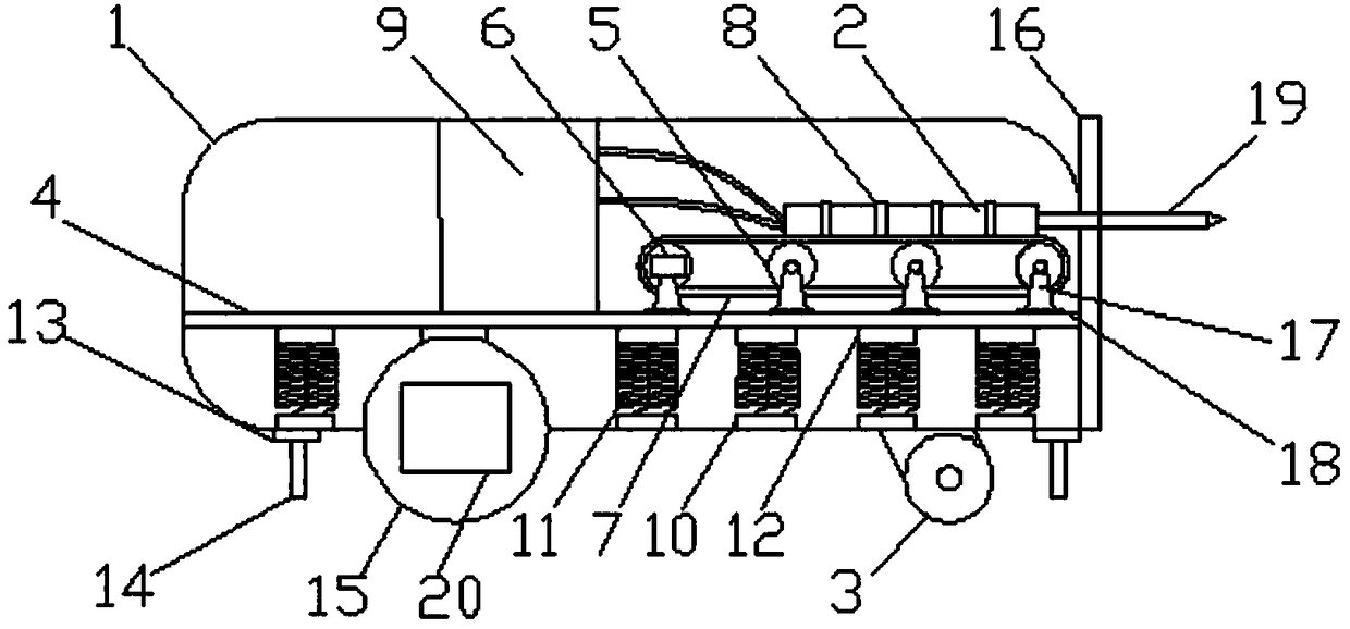
[0026] The embodiment of the invention discloses a hydraulic drill that is easy to move, and the hydraulic drill is detachable, suitable for various construction environments, reducing the investment in drilling equipment and reducing production costs.

[0027] A hydraulic drill that is easy to move, comprising: a box body 1, an actuator and a running mechanism; the bottom of the box body 1 is equipped with a running mechanism; the actuator is placed in the box...


PUM


Abstract

The invention discloses a hydraulic drill convenient to move. The hydraulic drill includes a box body, an execution mechanism and a walking mechanism. The walking mechanism is installed at the bottomof the box body; the execution mechanism is arranged in the box body; the walking mechanism includes a driving wheel and a driven wheel; a motor is connected to the driving wheel, and the driving wheel drives the driven wheel to rotate. In the execution mechanism, a mounting plate is connected with the bottom of the box body through a damping connector; at least two brackets are mounted on the upper surface of the mounting plate; rolling shafts are supported by the brackets and driven by a hydraulic motor; the brackets are cooperatively arranged with the rolling shafts; a caterpillar band is matched with the rolling shafts, and the rolling shafts drive the caterpillar band to move; a hydraulic drill body is fixed to the upper surface of the caterpillar band through fixing rings; a hydraulic drill controller is electrically connected with the hydraulic drill body. According to the disclosed hydraulic drill convenient to move, not only is convenience provided for movement, but also the hydraulic drill is detachable and applicable to different kinds of construction environments, investment of drilling equipment is decreased, and the production cost is reduced.

Description

technical field [0001] The invention relates to the technical field of excavation, in particular to a hydraulic drill which is easy to move. Background technique [0002] In the prior art, construction equipment, such as drilling rigs, has a short drilling stroke during the construction process. Generally, the longest common equipment is no more than 5 meters, and its efficiency is low; it will generate a lot of mud and dust pollution; when drilling intensively, It is difficult to accurately and quickly align the hole positions; the available drilling technology is single, which cannot meet the drilling construction needs of various complex strata; the drilling rig power system is single, and the construction conditions are high. [0003] In particular, the existing drilling rig equipment is highly targeted, and generally can only cope with a single terrain and the surrounding environment of the construction. It is difficult to maintain continuous and stable work when the te...

Claims


Application Information

Patent Timeline
IPC IPC(8): E21B7/02E21B3/02E21B44/00
CPCE21B3/02E21B7/02E21B7/022E21B44/00
Inventor 张光权叶义成王其虎
Owner WUHAN UNIV OF SCI & TECH
Learn More