An automatic wall-moving handrail for geriatric nursing

An armrest and automatic technology, applied in the field of medical care, can solve problems such as safety, hidden dangers, and inability to be supported

Active Publication Date: 2021-09-14
FOURTH MILITARY MEDICAL UNIVERSITY
View PDF6 Cites 0 Cited by
  • Summary
  • Abstract
  • Description
  • Claims
  • Application Information

AI Technical Summary

Problems solved by technology

The current wall-moving armrests are all fixed installation structures, which cannot be installed in some areas, resulting in intermittent unsupported situations during the walking process of patients, for example, at the entrances and exits, ward doors, etc. If the handrail is installed on the wall, if the patient needs to continue walking, there is no way to be supported, which poses a safety hazard and needs to be improved urgently

Method used


Image

  • An automatic wall-moving handrail for geriatric nursing
  • An automatic wall-moving handrail for geriatric nursing
  • An automatic wall-moving handrail for geriatric nursing

Examples


specific Embodiment approach 1

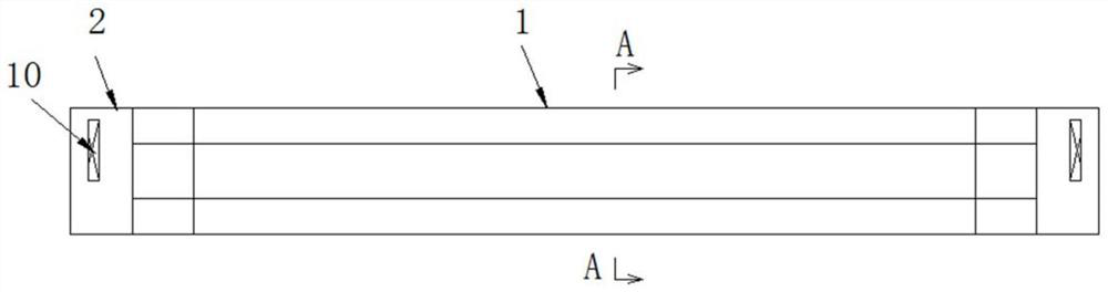
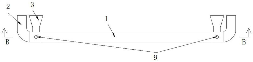
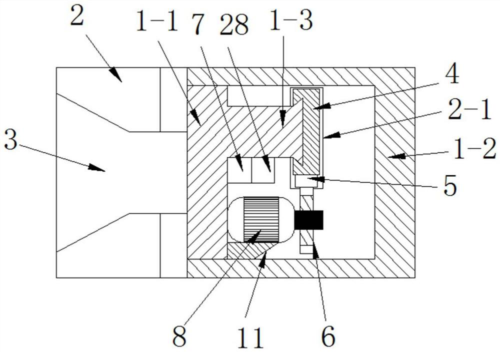
[0024] Such as Figure 1-Figure 6 As shown, this specific embodiment adopts the following technical scheme: it includes a handrail body 1, an elbow 2 and a fixing seat 3; Fixed seat 3, the inner end surface of fixed seat 3 is flush with the inner end surface of elbow 2; it also includes adjustable armrest 4, No. 1 rack 5, No. 1 gear 6, power supply 7, and No. 1 forward and reverse motor 8 , control switch 9, controller 28 and infrared sensor 29; Described armrest body 1 is made of base plate 1-1 and outer cover plate 1-2; The front side cover of base plate 1-1 is provided with outer cover plate 1-2 , the middle part of the front side wall of the bottom plate 1-1 is integrally formed with a guide slide bar 1-3, and the front end of the guide slide bar 1-3 is a dovetail structure, and the dovetail structure slides and is set on the dovetail set on the back of the adjustable armrest 4 In the groove 4-1, the upper surface of the adjustable armrest 4 is glued and fixed with anti-c...

specific Embodiment approach 2

[0032] see Figure 7 The difference between this embodiment and Embodiment 1 is that the back of the base plate 1-1 is riveted and fixed with a slide rail 22, on which a slide block 21 is slidably arranged, and the slide block 21 The back side utilizes screw riveting to be fixed with No. 2 forward and reverse motor 20, and No. 2 gear 26 is fixed on the output end of No. 2 forward and reverse motor 20, and No. 2 gear 26 and No. It is integrally formed on the back side of the base plate 1-1. The upper part of the No. 2 forward and reverse motor 20 is fixed with a sterile cotton mounting plate 23 by means of a connecting rod 25. The sterile cotton 24 is embedded in the bottom of the sterile cotton mounting plate 23. The bottom surface of the sterile cotton 24 It is arranged on the upper surface of the outer cover plate 1-2; the above-mentioned No. 2 forward and reverse motor 20 is electrically connected to the power supply 7; the rest of the structure and connection relationship ...


PUM


Abstract

An automatic wall-moving handrail for geriatric care. The invention relates to the field of medical care technology. The No. 1 gear is fixed on the output end of the No. 1 forward and reverse motor, the No. The rotating motor is electrically connected with the power supply, and the power supply is fixed on the bottom plate. The No. 1 forward and reverse motor is electrically connected with two control switches. The two control switches are respectively embedded in the left and right ends of the top wall of the outer cover. The left and right ends are embedded with infrared sensors, the infrared sensors are connected to the controller, the controller is connected to the control switch, and the controller is fixed on the bottom wall of the guide slide bar; the outer wall of the elbow is provided with a groove The above-mentioned adjustable armrest is movable in the notch. It can provide a temporary support function at places where there is no way to install it, such as entrances and exits, ward doors, etc., to provide full support for patients to move forward and improve safety.

Description

technical field [0001] The invention relates to the technical field of medical care, in particular to an automatic wall-moving handrail for geriatric care. Background technique [0002] The moving wall handrail is a structure used to provide support for patients to walk around in hospitals or rehabilitation centers. The current wall-moving armrests are all fixed installation structures, which cannot be installed in some areas, resulting in intermittent unsupported situations during the walking process of patients, for example, at the entrances and exits, ward doors, etc. If the handrail of the wall is installed, if the patient needs to continue walking at this time, there is no way to be supported, and there is a potential safety hazard, which needs to be improved urgently. Contents of the invention [0003] The object of the present invention is to aim at the defects and deficiencies of the prior art, to provide a reasonably designed automatic wall-moving handrail for ge...

Claims


Application Information

Patent Timeline
Patent Type & Authority Patents(China)
IPC IPC(8): E04F11/18
CPCE04F11/1802E04F11/1808E04F2011/1868E04F2011/1876
Inventor 张婷
Owner FOURTH MILITARY MEDICAL UNIVERSITY
Why Eureka
Try Eureka