
An ultra-high-definition imaging optical system

An optical system, image-side technology, applied in optics, optical components, instruments, etc., can solve problems such as low resolution

Active Publication Date: 2021-04-16
NINGBO YONGXIN OPTICS
View PDF5 Cites 0 Cited by
  • Summary
  • Abstract
  • Description
  • Claims
  • Application Information

AI Technical Summary

Problems solved by technology

However, the resolution of existing vehicle optical systems is generally low, and the front-view lenses currently popular in the market are usually one million or two million pixels.

Method used


Image

  • An ultra-high-definition imaging optical system
  • An ultra-high-definition imaging optical system
  • An ultra-high-definition imaging optical system

Examples


Embodiment

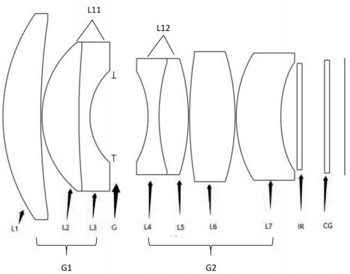
[0018] This example figure 1 Shown: From the object plane to the image plane, the first lens L1 with positive power, the second lens L2 with positive power, the third lens L3 with negative power, and the lens with negative power Fourth lens L4, fifth lens L5 with positive power, sixth lens L6 with positive power, seventh lens L7 with positive power, filter IR, chip protection glass CG, third lens A diaphragm G is set between the lens L3 and the fourth lens L4. The first lens L1 is a meniscus structure with a convex surface on the object side, the second lens L2 is a meniscus structure with a convex surface on the object side, and the third lens L3 is a convex surface on the object side. is a convex meniscus structure, the fourth lens L4 is a biconcave surface, the fifth lens L5 is a biconvex surface, the sixth lens L6 is a biconvex surface, the seventh lens L7 is a meniscus structure with a convex surface on the object side, the second lens L2 and The third lens L3 is cemente...


PUM

PropertyMeasurementUnit
viewing angleaaaaaaaaaa

Abstract

The invention discloses an ultra-high-definition imaging optical system. Through the hybrid design of seven spherical surfaces and aspheric surfaces, with reasonable focal power and reasonable parameter matching, the optical system of the present invention is guaranteed to have a sufficiently large image height, and To achieve ultra-high resolution, the optical system design can maintain stable imaging performance at ‑40-115 °C.

Description

technical field [0001] The invention relates to an imaging optical system, in particular to an ultra-high-definition imaging optical system. Background technique [0002] With the application and popularization of automotive safety driving systems, there are more and more lens requirements for applications such as front vehicle collision warning, track deviation warning, and pedestrian recognition warning. Such lenses need to have higher imaging resolution. However, the resolution of the existing vehicle-mounted optical systems is generally low, and the front-view lenses popular in the market are usually one million or two million pixels. Contents of the invention [0003] The technical problem to be solved by the present invention is to provide an ultra-high-definition imaging optical system that can meet the requirements of the market for ultra-high-definition lenses, and the maximum pixel can reach 8 million. [0004] The technical solution adopted by the present inven...

Claims


Application Information

Patent Timeline
Patent Type & Authority Patents(China)
IPC IPC(8): G02B13/00G02B13/18
CPCG02B13/0045G02B13/18
Inventor 张丽芝毛磊陈金珠孙秀云喻军章奕清吕威
Owner NINGBO YONGXIN OPTICS
Learn More