Crankshaft bending torsion combined load test device

A composite load and test device technology, applied in the direction of measuring device, testing material strength by applying stable bending force, testing material strength by applying stable torsion force, etc., to achieve accurate results

Active Publication Date: 2021-01-29
ZHEJIANG UNIV
View PDF9 Cites 2 Cited by
  • Summary
  • Abstract
  • Description
  • Claims
  • Application Information

AI Technical Summary

Problems solved by technology

[0003] In order to overcome the deficiency that the existing crankshaft bending and torsion test bench cannot apply alternating bending moment loads, the present invention provides a crankshaft bending and torsion composite load test device, which can not only pass through the vibration exciter and the vibrating rod Pulsating torque can be applied, and alternating bending moment can be applied through the motor and eccentric wheel device to achieve an effect closer to the real force of the crankshaft

Method used


Image

  • Crankshaft bending torsion combined load test device
  • Crankshaft bending torsion combined load test device
  • Crankshaft bending torsion combined load test device

Examples


Embodiment Construction

[0014] The present invention will be further elaborated below in conjunction with the accompanying drawings and embodiments.

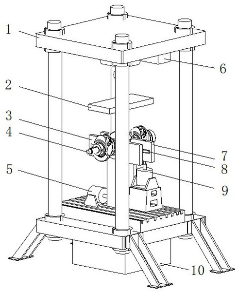
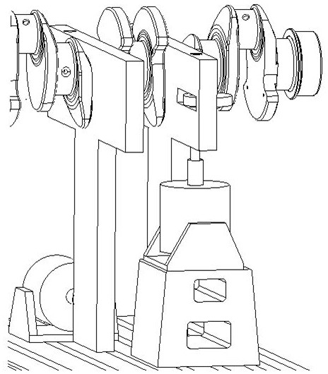
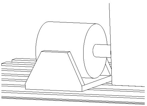
[0015] Such as figure 1 As shown, the test bench in the present invention includes a bench 1, a hanger 2, a torsion fixture 3, an exciter 5, a slide rail 6, a bending fixture 7, an eccentric wheel 8, a motor 9, an electric control cabinet 10 (including a power amplifier , function generator, dynamic strain gauge); the stand 1 is four-column-shaped, with two upper and lower platforms, the slide rail 6 for horizontal sliding is arranged on the lower surface of the upper platform, the electric control cabinet 10 is located under the lower platform, and the vibration exciter 5. The motor 9 is located above the lower platform; the slider on the slide rail 6 is connected to the hanger 2, and the hanger 2 is used to hang the torsion fixture 3 and the bending fixture 7, and the torsion fixture 3 and the bending fixture 7 are used to fix the crankshaft sample ...


PUM


Abstract

The invention discloses a crankshaft bending torsion combined load test device. A rack serves as a support, and a sliding rail, a lifting appliance, a bending clamp, a torsion clamp, a vibration exciter, a motor, an eccentric wheel and an electric control cabinet (comprising a power amplifier, a function generator and a dynamic strain gauge) are arranged in the rack. According to the invention, atorsion clamp and a bending clamp are lifted through a lifting appliance and a sliding rail, a crankshaft sample piece is fixed through the bending clamp and the torsion clamp, so that a proper test position is obtained on the rack, a vibration exciter vibration rod drives the torsion clamp to apply pulsating torque to the crankshaft, and the motor and the eccentric wheel drive the bending clamp to apply alternating bending moment to the crankshaft. During testing, frequency and amplitude signals are set and pass through the signal generator and the power amplifier, the vibration exciter and the motor are driven to output, so that the crankshaft is forced to vibrate, the output power is further adjusted and the vibration frequency is changed after resonance is realized, and the fatigue strength condition of the crankshaft is judged and analyzed through data of the strain gauge.

Description

technical field [0001] The invention relates to a crankshaft bending and torsion composite load test device, in particular to a crankshaft bending and torsion composite load test device which can independently apply pulsating torque and alternating bending moment to the crankshaft at the same time to carry out the crankshaft fatigue simulation test. Background technique [0002] At present, the known structure of the crankshaft bending and torsion test bench is formed by connecting a support stand, a hanger, a bending fixture, a torsion fixture, an exciter, and an electric control cabinet. Through the excitation signal generated by the exciter, the vibrating rod drives the bending fixture and the torsion fixture to apply pulsating bending moment and torque to the crankshaft. However, under the actual stress state of the crankshaft, the torque is a pulsating load and the bending moment is an alternating load. The alternating bending moment load cannot be generated only by the...

Claims


Application Information

Patent Timeline
Patent Type & Authority Applications(China)
IPC IPC(8): G01M7/02G01M13/00G01N3/04G01N3/20G01N3/22
CPCG01M7/00G01M13/00G01N3/22G01N3/20G01N3/04
Inventor 刘震涛颜睿东张威刁子宇张艳艳闻华殿李科阳葛广彬刘凯华孙美瑶袁野阳若淼
Owner ZHEJIANG UNIV
Why Eureka
Try Eureka