Dynamic coded lock based on Internet of Things

A dynamic password lock and Internet of Things technology, applied in the field of password locks, can solve the problems of single password, power consumption, password leakage, etc., and achieve the effect of convenient use and prolonging the service life

Inactive Publication Date: 2021-01-29
江苏燕鸥研学云数据科技有限责任公司
View PDF0 Cites 0 Cited by
  • Summary
  • Abstract
  • Description
  • Claims
  • Application Information

AI Technical Summary

Problems solved by technology

[0002] Combination locks are mainly used to store documents, valuables, disks, etc. They are more common in companies, banks and other places, and are widely used. The traditional mechanical combination lock password is relatively simple and easy to leak, and the high-precision mechanical combination lock is too expensive. , with the continuous development of science and technology, the types of various locks are increasing, and the security performance of combination locks is getting higher and higher. Combination locks are gradually being applied to file cabinets, safes, and home doors, especially in commercial use. With the increasingly fierce business competition, people's awareness of the protection of documents and other items involving business secrets has gradually increased. Existing file cabinets or safes and other confidential places generally use key locks or combination locks. Others who want to open the door must Holding the key or knowing the password increases security to a certain extent, but these combination locks are too simple, and the password is basically fixed, so it is easy to cause password leakage after a long time, making the security of the combination lock relatively poor, so now Some use dynamic password locks to increase security, but as electronic products increase in usage, the internal power supply will be continuously consumed, resulting in failure to open, etc.

Method used


Image

  • Dynamic coded lock based on Internet of Things
  • Dynamic coded lock based on Internet of Things
  • Dynamic coded lock based on Internet of Things

Examples


Embodiment Construction

[0023] The implementation of the present application will be described in detail below with reference to the accompanying drawings and examples, so as to fully understand and implement the implementation process of how the present application uses technical means to solve technical problems and achieve technical effects.

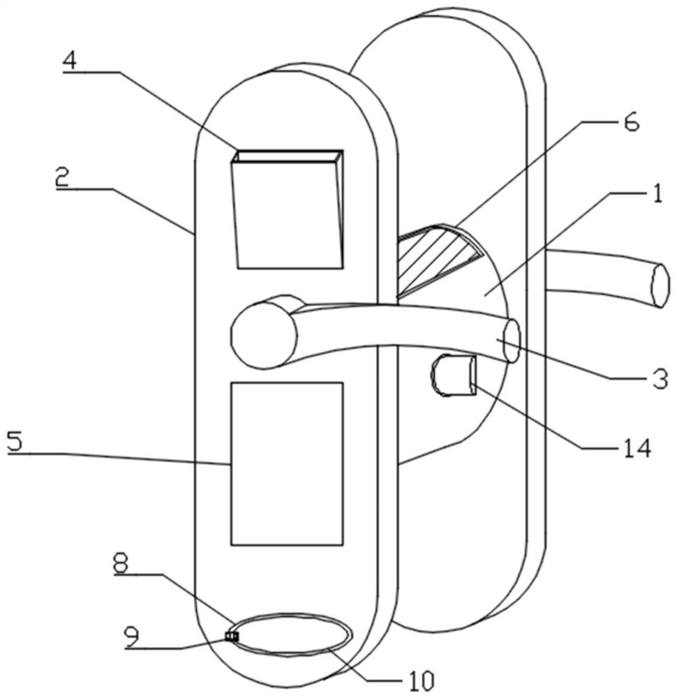
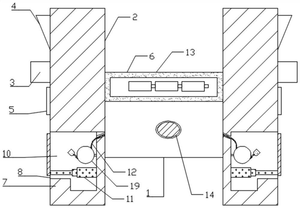
[0024] like Figure 1-Figure 4 As shown, this embodiment provides a dynamic password lock based on the Internet of Things, including a lock body 1 and a cover plate 2, the two ends of the lock body 1 are connected to the cover plate 2, and the cover plate 2 is far away from one side of the lock body 1 There is a handle 3 on the side, and a storage tank 4 is arranged above the handle 3. The storage tank 4 plays the role of storing items. The opening of the upper end of the storage tank 4 is larger than the bottom, which makes it more convenient to put in and take out items. It will be more eye-catching and easy to see, the password input plate 5 is arranged u...


PUM


Abstract

The invention relates to the technical field of coded locks, and in particular relates to a dynamic coded lock based on the Internet of Things. The dynamic coded lock comprises a lock body and covering plates, the two ends of the lock body are connected with the covering plates, one side of each covering plate is provided with a handle, a storage groove is formed above each handle, a password input disc is arranged below each handle, the lower end of each covering plate is provided with a wire storage groove, a through hole is formed in one side of each wire storage groove, one end of each through hole is connected with a wire duct cover, one end of each wire duct cover is provided with a rebounding device, a charging wire is arranged in each wire storage groove, a power supply device is arranged on the upper end face of the lock body, the charging wires are electrically connected with the power supply device, a spring bolt is arranged on one side of the lock body, a groove is formed in one end of the spring bolt, a rubber layer is connected into the groove through a connecting column, and a spring is arranged on the outer side of the connecting column in a sleeving mode. The charging wires electrically connected with the power supply device are arranged on the covering plates on the two sides of the lock body, equipment is charged on the outer side when the electric quantity of the power supply device is used up, and use is more convenient.

Description

technical field [0001] The invention relates to a dynamic combination lock, in particular to a dynamic combination lock based on the Internet of Things, and belongs to the technical field of combination locks. Background technique [0002] Combination locks are mainly used to store documents, valuables, disks, etc. They are more common in companies, banks and other places, and are widely used. The traditional mechanical combination lock password is relatively simple and easy to leak, and the high-precision mechanical combination lock is too expensive. , with the continuous development of science and technology, the types of various locks are increasing, and the security performance of combination locks is getting higher and higher. Combination locks are gradually being applied to file cabinets, safes, and home doors, especially in commercial use. With the increasingly fierce business competition, people's awareness of the protection of documents and other items involving bus...

Claims


Application Information

Patent Timeline
Patent Type & Authority Applications(China)
IPC IPC(8): G07C9/00
CPCG07C9/00174G07C9/00896G07C9/00944G07C2009/00634
Inventor 朱启峰
Owner 江苏燕鸥研学云数据科技有限责任公司
Why Eureka
Try Eureka