

Refrigerator
A refrigerator and door body technology, applied in the field of refrigerators, can solve the problems of unsatisfactory fresh-keeping effect of refrigerators, achieve the effect of ensuring the integrity of the appearance and expanding the range of fresh-keeping
- Summary
- Abstract
- Description
- Claims
- Application Information
AI Technical Summary
Problems solved by technology
Method used
Image

Examples
Embodiment 1
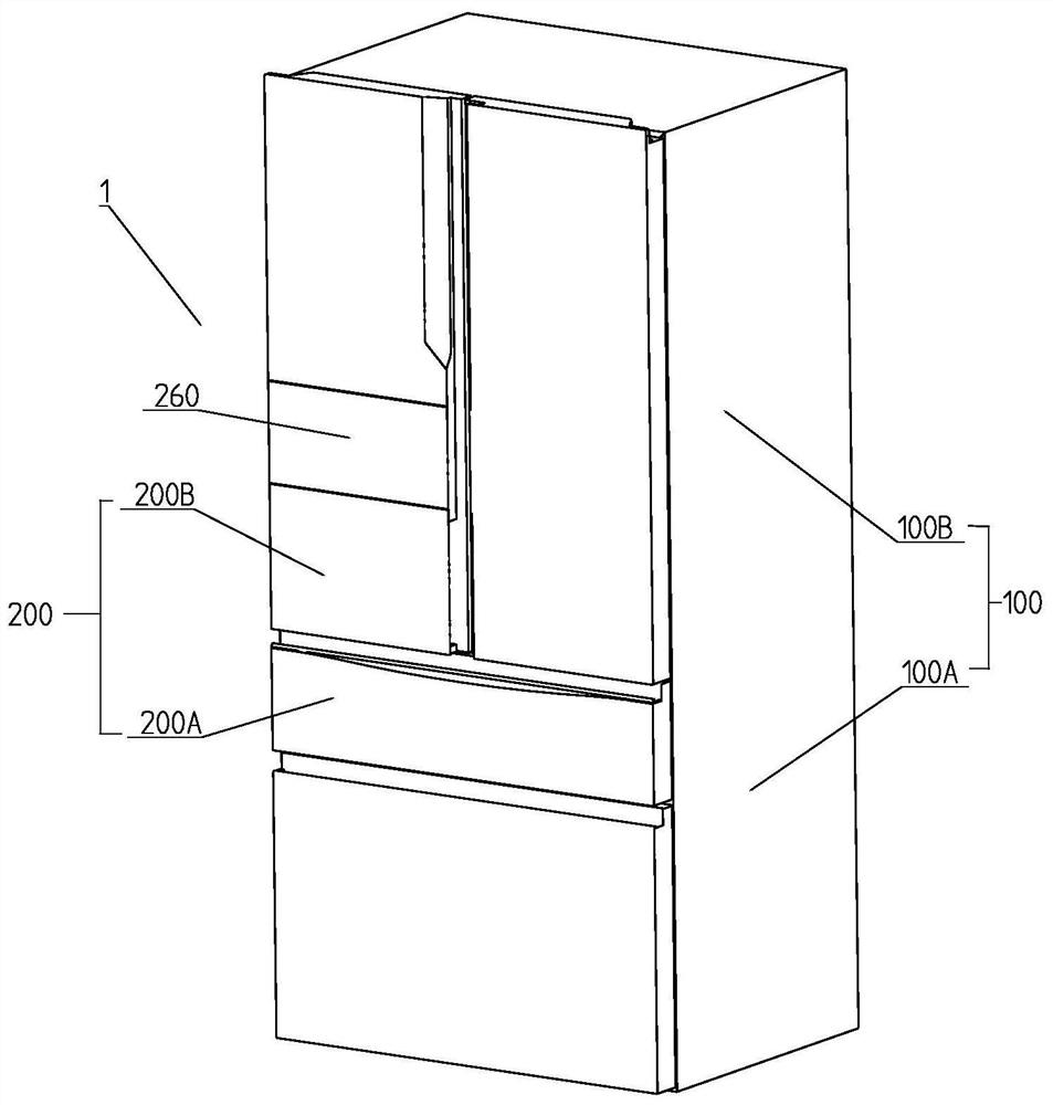
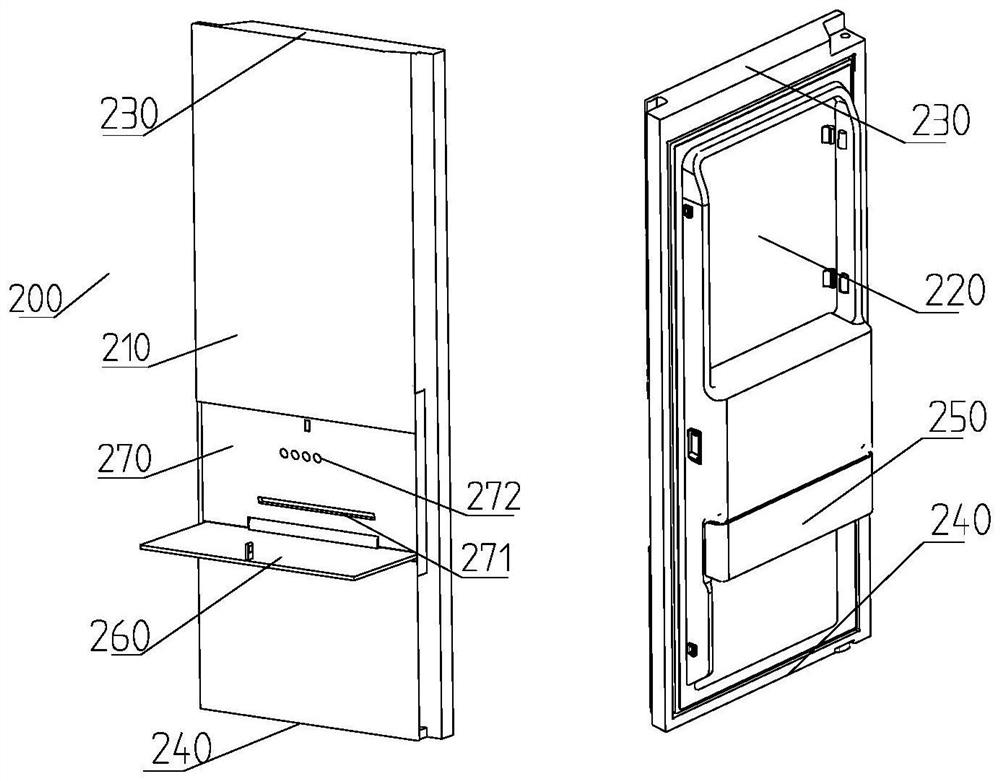
[0054] figure 1 It is a perspective view of a specific embodiment of the refrigerator of the present invention; refer to figure 1 , the refrigerator 1 of the present embodiment has an approximately rectangular parallelepiped shape. The appearance of the refrigerator 1 is defined by a storage room 100 defining a storage space and a plurality of doors 200 provided in the storage room 100, wherein, referring to figure 2 The door body 200 includes a door body casing 210 located outside the storage room 100, a door inner container 220 located inside the storage room 100, an upper end cover 230, a lower end cover 240, and a door body outer casing 210, a door inner container 220, The heat insulating layer between the upper end cover 230 and the lower end cover 240; usually, the heat insulating layer is filled with foam material.
[0055] The storage room 100 has an open box, and the storage room 100 is vertically divided into a lower freezing room A and an upper cooling room 100B....
Embodiment 2
[0092] The structure of the second embodiment is basically the same as that of the first embodiment, the difference lies in the connection method between the lower support 310 and the small heat preservation door 250 . Specifically, in this embodiment, refer to Figure 24A , Figure 24B As shown, the lower support 310 is detachably connected to the small heat preservation door 250 . Such as Figure 25 As shown, the small thermal insulation door 250 is formed by a first shell 251 and a second shell 252 with an open cavity structure and an insulating member disposed between the first shell 251 and the second shell 252 . Wherein, the first housing 251 is snap-connected with the second housing 252, the first housing 251 is provided with an extension arm 2511 in a direction away from the second housing 252, and the lower support 310 is detachably connected. on the extension arm 2511 .
[0093] Specifically, the end of the extension arm 2511 is formed with a first limiting porti...
Embodiment 3
[0099] The structure of this embodiment 2 is basically the same as that of the embodiment 1, the difference lies in the connection method between the lower support 310 and the small heat preservation door 250 and the door body 200 .
[0100] Such as Figure 26A-Figure 26C As shown, the lower support 310 and the small heat preservation door 250 are set independently of each other, and the lower side of the installation hole 201 is provided with a limiting part that limits the position of the lower support 310. The lower support 310 One end abuts against the limiting portion, and the other end abuts against the small heat preservation door 250 . The thermal insulation door 250 can be installed on the door body 200 by using the locking device 400 in the first or second embodiment.
PUM
 Abstract
Description
Claims
Application Information