An electric lock for operating a circuit

An operation loop and electrical lock technology, applied in the field of electrical locks, can solve the problems of increasing the number and cost of components, increasing the risk of operation failure, etc., and achieve the effect of reducing the total volume, reducing the risk of operation failure, and facilitating operation

Active Publication Date: 2022-06-28
NR ELECTRIC CO LTD +1
View PDF0 Cites 0 Cited by
  • Summary
  • Abstract
  • Description
  • Claims
  • Application Information

AI Technical Summary

Problems solved by technology

[0003] Problems in the existing technology: on the one hand, the exposed electrodes of the electric lock cannot avoid the vicious operation behavior of artificially illegally shorting and skipping the direct operation of the electric lock; on the other hand, setting both the electric lock and the button or switch not only increases Increased part count and cost, and increased risk of operational failure

Method used


Image

  • An electric lock for operating a circuit
  • An electric lock for operating a circuit
  • An electric lock for operating a circuit

Examples


Embodiment 1

[0050] like figure 2 , 3 , 4, 5, 6, an electrical lock for operating circuits, including:

[0051] housing 900,

[0052] The movable contact group 400, located in the housing 900, includes at least one conductor 403;

[0053] The static contact group 500, located in the housing 900, includes a first static contact 501 and a second static contact 502, and the first static contact 501 and the second static contact 502 are respectively connected to the operation Both ends of the loop to be turned on;

[0054] The elastic component 700 is arranged between the movable contact group 400 and the static contact group 500;

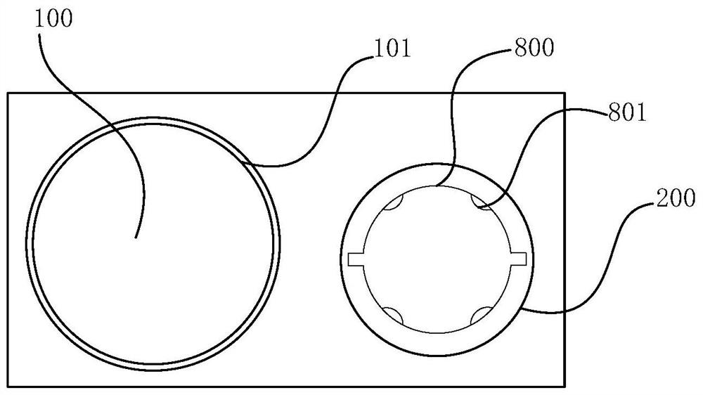
[0055] The button assembly 100 includes a button cap 101 and a pressing rod 102 , the button cap 101 is disposed on the top of the pressing rod 102 and at least partially outside the housing 700 , and the button assembly 100 passes through the button cap 101 and the pressing rod 102 transmits the external mechanical force to the movable contact group 400;

[0...

Embodiment 2

[0065] like figure 2 , 7 , 8 and 9, an electrical lock for operating circuits, including:

[0066] housing 900,

[0067] The movable contact group 400, located in the housing 900, includes at least one conductor 403;

[0068] The static contact group 500, located in the housing 900, includes a first static contact 501 and a second static contact 502, and the first static contact 501 and the second static contact 502 are respectively connected to the operation Both ends of the loop to be turned on;

[0069] The elastic component 700 is arranged between the movable contact group 400 and the static contact group 500;

[0070] The button assembly 100 includes a button cap 101 and a pressing rod 102 , the button cap 101 is disposed on the top of the pressing rod 102 and at least partially outside the housing 700 , and the button assembly 100 passes through the button cap 101 and the pressing rod 102 transmits the external mechanical force to the movable contact group 400;

...


PUM


Abstract

The invention discloses an electric lock for an operation circuit, comprising: a housing, a moving contact group, a static contact group, an elastic assembly, a button, and a lock cylinder assembly; the button includes a button cap and a pressing rod, and the The lock cylinder assembly includes a lock cylinder and a lock cylinder connecting rod. The lock cylinder connecting rod is arranged at the bottom of the lock cylinder and is rotatably arranged in the housing together with the lock cylinder. The lock cylinder connecting rod is controlled by the lock cylinder. The lock cylinder is driven, and the pressure rod can be controlled by the rotation of the lock cylinder connecting rod, so that the pressure rod is in a locked state or an unlocked state. The present invention avoids the problem that the operation circuit needs to be turned on twice by integrating the lock cylinder with the mechanical switch, and also reduces the number of components and the cost of use of the equipment, and also reduces the risk of operation failure; It is hidden inside the electric lock, and the mechanical switch directly or indirectly controls the conduction of the conduction part, which avoids the possibility of vicious operation caused by artificial short-circuiting of wires.

Description

technical field [0001] The invention relates to the technical field of substation error prevention, in particular to an electrical lock used for an operation circuit. Background technique [0002] as attached figure 1 As shown in the circuit diagram of , the prior art switch knife switch error prevention system generally connects both an electric lock and an ordinary operation button or a switch in series in the operation circuit to realize the on and off of the operation circuit. The usual operation process is that when opening and closing operations are required, first turn on the electrodes at both ends of the electrical lock through the computer key, and then press the operation button or turn the transfer switch to turn on the operating circuit to realize the opening and closing operation of the switch knife switch. [0003] Problems existing in the prior art: On the one hand, the exposed electrodes of the electrical lock cannot avoid the vicious operation behavior of ...

Claims


Application Information

Patent Timeline
Patent Type & Authority Patents(China)
IPC IPC(8): H01H9/20H01H27/06H01H71/10
CPCH01H9/20H01H27/06H01H71/10
Inventor 王敏熊慕文朱何荣任晨曦陈龙
Owner NR ELECTRIC CO LTD
Why Eureka
Try Eureka