
Electromagnetic input device and electromagnetic input method for recognizing interference

An input device and electromagnetic technology, which is applied in the field of electromagnetic induction, can solve problems such as high power consumption of the electromagnetic board, failure of the electromagnetic board, and random movement of the handwriting cursor function, and achieve the effect of improving fluency and accuracy

Active Publication Date: 2021-02-05
SHENZHEN HUION ANIMATION TECH
View PDF8 Cites 0 Cited by
  • Summary
  • Abstract
  • Description
  • Claims
  • Application Information

AI Technical Summary

Problems solved by technology

However, because the electromagnetic board has certain requirements on the stability of the power supply, if the power supply fails to meet the requirements, the electromagnetic board will not work stably or even fail to work, and such a handwriting board must be connected to PS / 2 and COM ports at the same time
In this way, the electromagnetic board cannot be used on some machines. At the same time, the electromagnetic board consumes too much power and is susceptible to electromagnetic interference from the external environment. can not work
[0004] When the existing electromagnetic handwriting device is placed in a scene with large interference, such as when it is placed on the keyboard, it will cause the handwriting cursor or function to fluctuate, which will interfere with the handwriting performance of the handwriting device, which is not conducive to the development of the electromagnetic handwriting device. Handwriting fluency and accuracy

Method used


Image

  • Electromagnetic input device and electromagnetic input method for recognizing interference
  • Electromagnetic input device and electromagnetic input method for recognizing interference
  • Electromagnetic input device and electromagnetic input method for recognizing interference

Examples


no. 1 example

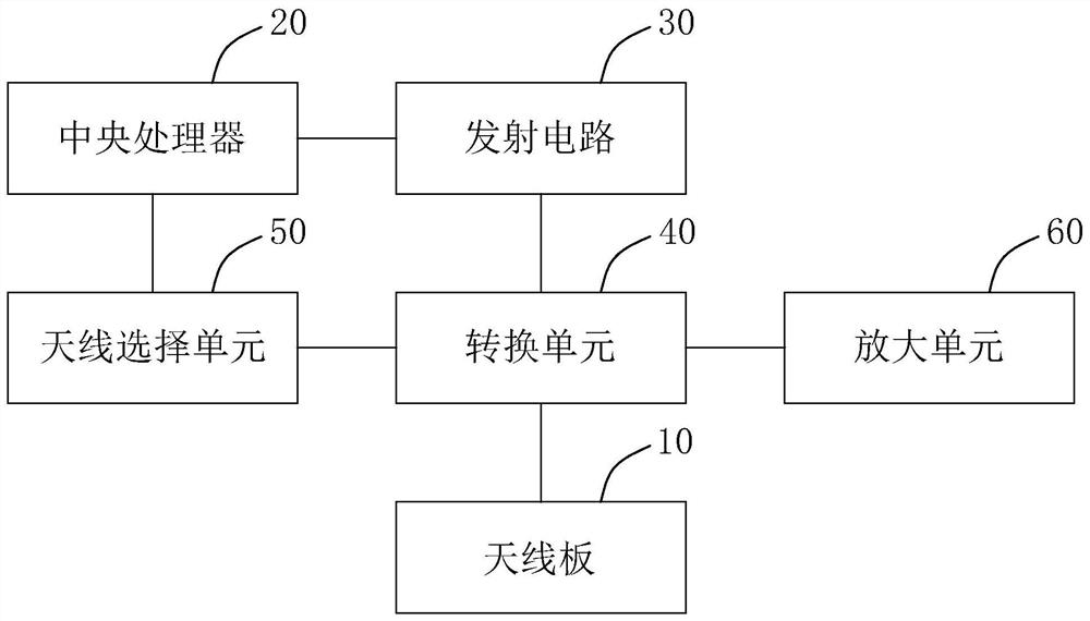
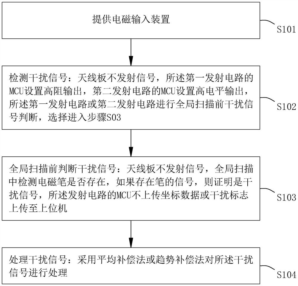
[0029] Please refer to figure 1 with figure 2 , the present invention also provides an electromagnetic input method for identifying interference, which includes the following steps:

[0030] Step S101, providing the aforementioned electromagnetic input device 100;

[0031] Step S102, detecting interference signals: the antenna board 10 does not transmit signals, the MCU of the first transmitting circuit sets a high-impedance output, the MCU of the second transmitting circuit sets a high-level output, and the first transmitting circuit or the second transmitting circuit Judgment of interference signals before the transmitting circuit performs global scanning;

[0032] Step S103, judging the interference signal before the global scan: the antenna board does not transmit a signal, check whether the electromagnetic pen exists during the global scan, if there is a pen signal, it proves to be an interference signal, and the MCU of the transmitting circuit does not upload coordina...

no. 2 example

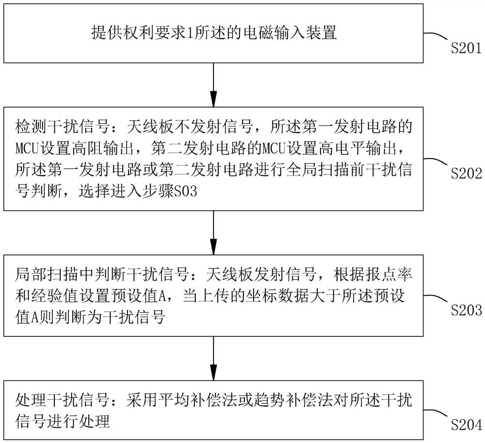
[0037] Please refer tofigure 1 with image 3 , image 3 The flow chart of the second embodiment of the electromagnetic input method for identifying interference provided by the present invention includes the following steps:

[0038] Step S201, providing the aforementioned electromagnetic input device 100;

[0039] Step S202, detecting interference signals: the antenna board does not transmit signals, the MCU of the first transmitting circuit sets a high-impedance output, the MCU of the second transmitting circuit sets a high-level output, and the first transmitting circuit or the second transmitting circuit performs Judgment of interference signal before global scanning, choose to enter step S203;

[0040] Step S203, judging the interference signal in partial scanning: the antenna board transmits the signal, and the preset value A is set according to the reporting rate and the experience value, and when the uploaded coordinate data is greater than the preset value A, it is ...

no. 3 example

[0043] Please refer to figure 1 with Figure 4 , Figure 4 It is a flow chart of the third embodiment of the electromagnetic input method for identifying interference provided by the present invention.

[0044] Step S301, providing the aforementioned electromagnetic input device 100;

[0045] Step S302, detecting interference signals: the antenna board does not transmit signals, the MCU of the first transmitting circuit sets a high-impedance output, the MCU of the second transmitting circuit sets a high-level output, and the first transmitting circuit or the second transmitting circuit performs Judgment of interference signal before global scanning, choose to enter step S303 or step S304;

[0046] Step S303, judging the interference signal before the global scan: the antenna board does not emit a signal, check whether the electromagnetic pen exists during the global scan, if there is a pen signal, it proves to be an interference signal, and the MCU of the transmitting circu...


PUM


Abstract

The invention provides an electromagnetic input device and an electromagnetic input method for recognizing interference, the electromagnetic input device comprises an antenna plate, a central processing unit connected with the antenna plate, and a transmitting circuit connected with the central processing unit, the transmitting circuit comprises a first transmitting circuit and a second transmitting circuit, the first transmitting circuit is a high-resistance output circuit, and the second transmitting circuit is a high-level output circuit. The electromagnetic input method comprises the stepsof providing the electromagnetic input device, detecting an interference signal, judging the interference signal before global scanning, judging the interference signal in local scanning and processing the interference signal. According to the electromagnetic input device and the electromagnetic input method for recognizing interference, the problem that electromagnetic handwriting is interferedby electromagnetic interference can be solved while the report rate of electromagnetic handwriting is not affected, and the smoothness and accuracy of electromagnetic handwriting are improved.

Description

【Technical field】 [0001] The invention relates to the technical field of electromagnetic induction, in particular to an electromagnetic input device and an electromagnetic input method for identifying interference. 【Background technique】 [0002] In the existing electromagnetic pressure sensing technology, there is a layer of circuit board (such as a keyboard) under the handwriting board in some application places. After the circuit is powered on, a magnetic field will be generated in a certain range in the antenna of the handwriting board. It can also be used in the stylus. A magnetic field is generated. Since the electromagnetic wave can be transmitted through the air, the magnetic field can be sensed even if the stylus is not in contact with the tablet during use, so there will be errors in determining the position of the stylus. The handwriting tablet after this patented technology solves the wrong position coordinates, and it writes smoothly, and can sense the pressure ...

Claims


Application Information

Patent Timeline
Patent Type & Authority Applications(China)
IPC IPC(8): G06F3/046
CPCG06F3/046Y02D30/70G06F3/0418G06F3/03545G06F3/038G06F3/04162
Inventor 不公告发明人
Owner SHENZHEN HUION ANIMATION TECH
Learn More