
Material drawing claw structure of novel glazing bead saw

A technology of glass beading and material claws, which is applied in metal processing and other directions, and can solve the problems of production efficiency decline and production cost increase

Pending Publication Date: 2021-02-09
JINAN CGMA CNC MACHINERY CO LTD
View PDF0 Cites 0 Cited by
  • Summary
  • Abstract
  • Description
  • Claims
  • Application Information

AI Technical Summary

Problems solved by technology

The gripping claw is firm and convenient, which has a great impact on the production cost and production time of the enterprise
[0004] During the use of general CNC glass bead saws, the suction grip cannot handle various profiles reliably, and the clamping mold needs to be customized according to the outer contour of the cut glass bead.
When producing a variety of doors and windows, it is necessary to prepare a variety of clamping molds, resulting in an increase in production costs and a decrease in production efficiency

Method used


Image

  • Material drawing claw structure of novel glazing bead saw

Examples


Embodiment Construction

[0014] In order to make the object, technical solution and advantages of the present invention clearer, the implementation manner of the present invention will be further described in detail below in conjunction with the accompanying drawings.

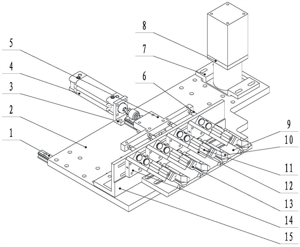
[0015] Such as figure 1 As shown in the drawing, a new type of drawing claw structure for glass bead saw, including a square rail 1, a supporting plate 2, and a pressing cylinder 11, the supporting plate 2 is installed on the slider, and the supporting plate 2 is installed with a servo Motor 8, the cylinder block 3 is installed on the supporting plate 2 by bolts, the cylinder 4 is installed on the cylinder block 3, the cylinder rod on the cylinder 4 is connected to the connecting plate 5 by bolts, and the other side of the connecting plate 5 is connected by bolts N feed shafts 6, the feed shaft 6 passes through the through hole on the support base 15, the other end of the feed shaft 6 is bolted to the feed head, the servo motor 8 is in...


PUM


Abstract

The invention discloses a material drawing claw structure of a novel glazing bead saw. A supporting plate of the material drawing claw mechanism is mounted on a sliding block of a guide rail, an air cylinder seat, a servo motor seat, a workbench plate and a supporting seat are mounted on the supporting plate through bolts, a feeding air cylinder is mounted on the air cylinder seat, an air cylinderrod on the feeding air cylinder is connected with a connecting plate through a bolt, n feeding shafts are connected to the other side of the connecting plate through bolts, feeding heads are connected to the other ends of the feeding shafts through bolts, a servo motor is mounted on the servo motor seat, adjustable backup plates are mounted on the workbench plate through bolts, adjustable adjusting plates are installed on the supporting seat through bolts, pressing air cylinders move along with the adjusting plates, and a pressing block is mounted on a pressing air cylinder rod of each pressing air cylinder. The material drawing claw structure has the beneficial effects that after a glazing bead section bar is placed, the positions of the pressing blocks and the backup plates are adjustedto be matched with the glazing bead section bar, then the debugging of the material drawing claw can be completed, and further, the cost and production time of a customized mold are saved.

Description

technical field [0001] The invention relates to the technical field of aluminum-plastic door and window mechanical equipment, in particular to a new-type pulling claw mechanism of a glass bead saw. Background technique [0002] The machine tool industry is the basic industry of the manufacturing industry, and numerical control equipment is the core product of the machine tool industry. With the intensive and standardized development of door and window processing enterprises, more and more large and medium-sized door and window processing enterprises at home and abroad adopt stable, reliable and suitable for the use of the door and window industry. It is a production line with a high degree of automation, and the glass bead saw is the most critical step in the production line. It determines the cutting accuracy of the glass bead profile, and ultimately affects the overall quality of doors and windows. [0003] In the production and processing of doors and windows, various doo...

Claims


Application Information

Patent Timeline
IPC IPC(8): B26D7/04B26D7/06
CPCB26D7/04B26D7/0608
Inventor 高振华
Owner JINAN CGMA CNC MACHINERY CO LTD
Learn More