

Driver monitoring method based on steering wheel, steering wheel and electronic equipment
Patent Information
- Authority / Receiving Office
- CN · China
- Current Assignee / Owner
- EVERGRANDE NEW ENERGY AUTOMOTIVE INVESTMENT HLDG GRP CO LTD
- Publication Date
- 2021-02-09
- Estimated Expiration
- Not applicable · inactive patent
Smart Images
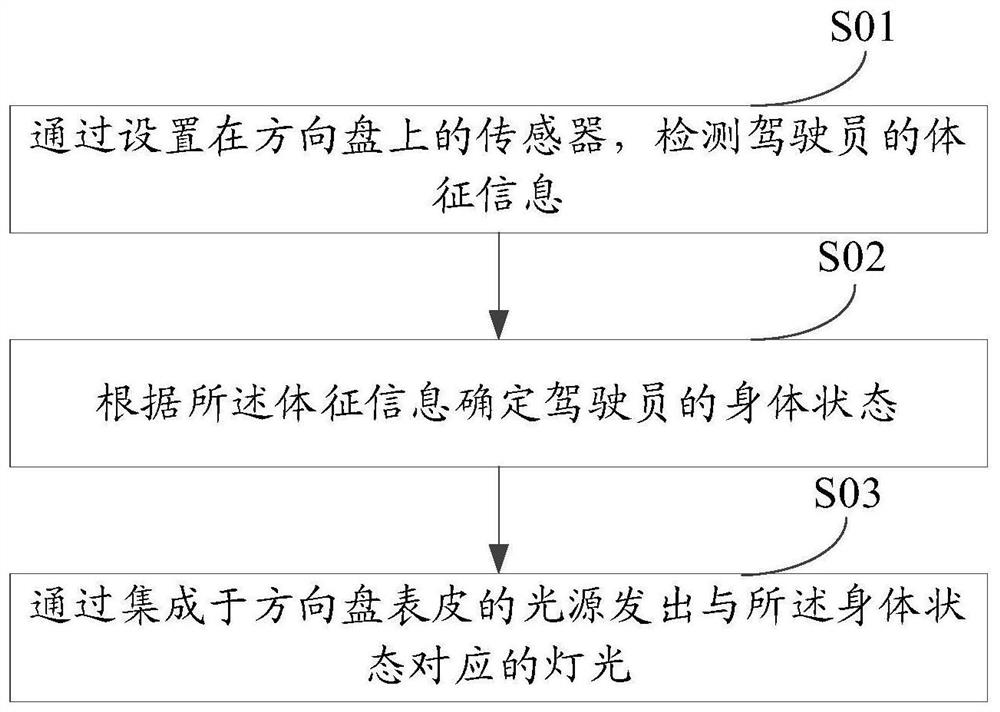
Figure 1 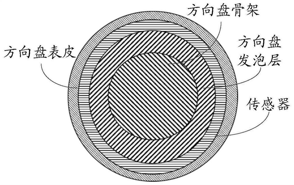
Figure 2 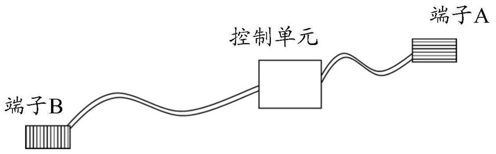
Figure 3
Abstract
Description
technical field
[0001] The invention relates to the technical field of vehicle driving, in particular to a steering wheel-based driver monitoring method, a steering wheel and electronic equipment. Background technique
[0002] For the color-changing steering wheel, in the existing technology, the method of arranging light strips is used to realize the lighting of the steering wheel. to control the brightness of the sense of direction.
[0003] The existing technology needs to occupy a narrow layout space of the steering wheel, and the light strip will block the sensitivity of the HOD sensor, resulting in failure to control the light. Contents of the invention
[0004] The purpose of the embodiments of the present invention is to provide a steering wheel-based driver monitoring method, steering wheel and electronic equipment to solve the problem that the existing technology needs to occupy a narrow layout space of the steering wheel, and the light strip will block the sens...