Electronic expansion valve control circuit and control method, air conditioner

An electronic expansion valve and control circuit technology, applied in the field of air conditioners, can solve problems such as difficulty in detecting the failure of an electronic expansion valve, and achieve the effects of avoiding incorrect replacement of faulty parts and effective short-circuit protection

Active Publication Date: 2021-11-05
GREE ELECTRIC APPLIANCES INC
View PDF0 Cites 0 Cited by
  • Summary
  • Abstract
  • Description
  • Claims
  • Application Information

AI Technical Summary

Problems solved by technology

[0005] Embodiments of the present invention provide a control circuit and control method of an electronic expansion valve, and an air conditioner, so as to at least solve the technical problem that the failure of the electronic expansion valve is difficult to detect in the prior art

Method used


Image

  • Electronic expansion valve control circuit and control method, air conditioner
  • Electronic expansion valve control circuit and control method, air conditioner
  • Electronic expansion valve control circuit and control method, air conditioner

Examples


Embodiment 1

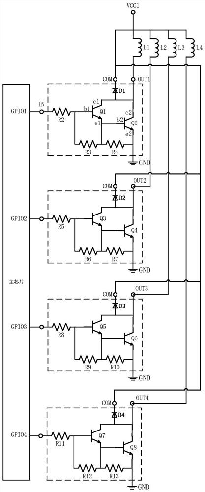
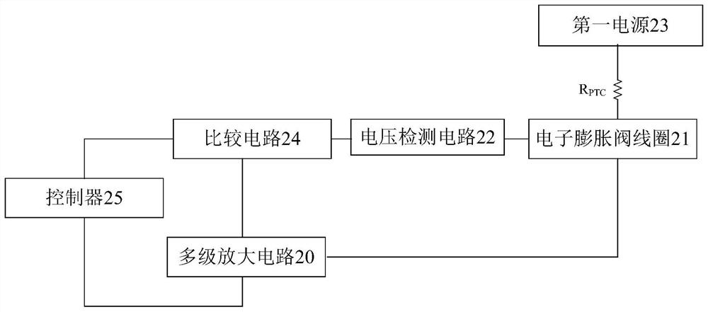
[0031] According to an embodiment of the present invention, a control circuit for an electronic expansion valve is provided, such as figure 2 , the above-mentioned control circuit includes: a multi-stage amplifier circuit 20, a coil 21 of an electronic expansion valve and a first power supply 23, and the first end of the coil 21 passes through a thermistor R PTCThe first power supply 23 is connected, and the second end of the coil 21 is connected to the collector of the last triode in the multi-stage amplifying circuit 20. The control circuit also includes: a voltage detection circuit 22 for detecting the ground voltage of the first end of the coil Comparing circuit 24, the noninverting input terminal of comparing circuit 24 is connected with voltage detection circuit 22, and the inverting input terminal of comparing circuit 24 is connected to a preset stable voltage, and comparing circuit 24 is used to convert the ground voltage of the first end of coil 21 Compare with the p...

Embodiment 2

[0057] According to an embodiment of the present invention, an embodiment of a control method for an electronic expansion valve is provided. It should be noted that the steps shown in the flowcharts of the accompanying drawings can be executed in a computer system such as a set of computer-executable instructions, and , although a logical order is shown in the flowcharts, in some cases the steps shown or described may be performed in an order different from that shown or described herein.

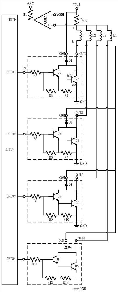
[0058] The electronic expansion valve control method of the embodiment of the present invention is applied to image 3 The control circuit of the electronic expansion valve, the control circuit includes: a multi-stage amplifier circuit, the coil L1-L4 of the electronic expansion valve and the first power supply VCC1, the first end a of the coil passes through the thermistor R PTC The first power supply VCC1 is connected, and the second end b of the coil is connected to the collector of the ...


PUM


Abstract

The invention discloses a control circuit and a control method of an electronic expansion valve and an air conditioner. Wherein, the control circuit includes a multi-stage amplifying circuit, a coil of the electronic expansion valve, and a first power supply; a voltage detection circuit for detecting the ground voltage at the first end of the coil; a comparison circuit for comparing the non-inverting input end of the circuit with the voltage The detection circuit is connected, the inverting input terminal of the comparison circuit is connected to the preset stable voltage, and the comparison circuit is used to compare the ground voltage at the first end of the coil with the preset stable voltage and output the comparison result for indicating Whether the coil is short-circuited; the controller is connected to the control terminal of the multi-stage amplifying circuit, and is connected to the output terminal of the comparison circuit, and is used to output to the control terminal of the multi-stage amplifying circuit when the comparison result indicates that the coil is short-circuited. Low level, used to disconnect the control signal to the electronic expansion valve. The invention solves the technical problem that the failure of the electronic expansion valve is difficult to detect in the prior art.

Description

technical field [0001] The invention relates to the technical field of air conditioning, in particular to a control circuit and a control method of an electronic expansion valve, and an air conditioner. Background technique [0002] High-efficiency inverter air conditioners generally use electronic expansion valves to replace traditional capillary tubes as the throttling parts of air conditioners, which are used to precisely adjust the flow of refrigerant entering the evaporator to further improve the energy efficiency of air conditioners. Different from the capillary, the electronic expansion valve is a typical electromechanical integration component, which is divided into electrical part and mechanical part, and its working principle is more complicated than that of the capillary. [0003] Part of the coil parts of the electronic expansion valve will be infiltrated by condensed water for a long time, which will cause the insulation material of the coil to age and reduce it...

Claims


Application Information

Patent Timeline
Patent Type & Authority Patents(China)
IPC IPC(8): F25B41/34
CPCF25B2341/068F25B2600/2513
Inventor 张嘉鑫周伟刘超徐娟张广东
Owner GREE ELECTRIC APPLIANCES INC
Why Eureka
Try Eureka