Rotor of centrifugal machine

A technology of centrifuges and rotors, which is applied in centrifuges and other directions, and can solve the problems of card ejection failure, damage to centrifugal turntable, reagent card falling off, etc.

Active Publication Date: 2021-02-12
TIANJIN DEXIANG BIOTECHNOLOGY CO LTD
View PDF12 Cites 0 Cited by
  • Summary
  • Abstract
  • Description
  • Claims
  • Application Information

AI Technical Summary

Problems solved by technology

At present, when installing the reagent card on the centrifugal turntable of the centrifuge, the reagent card is usually pushed in from the outside of the centrifugal turntable and fixed by the buckle. When the buckle is not fastened or lo

Method used


Image

  • Rotor of centrifugal machine
  • Rotor of centrifugal machine
  • Rotor of centrifugal machine

Examples


Embodiment Construction

[0029] The technical solutions of the present invention will be described in further detail below with reference to the accompanying drawings and embodiments.

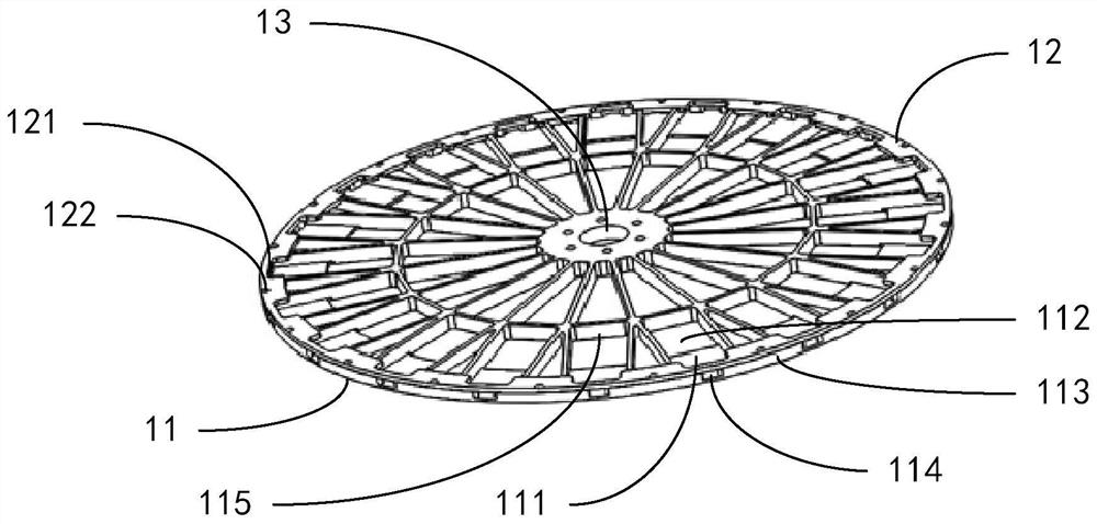
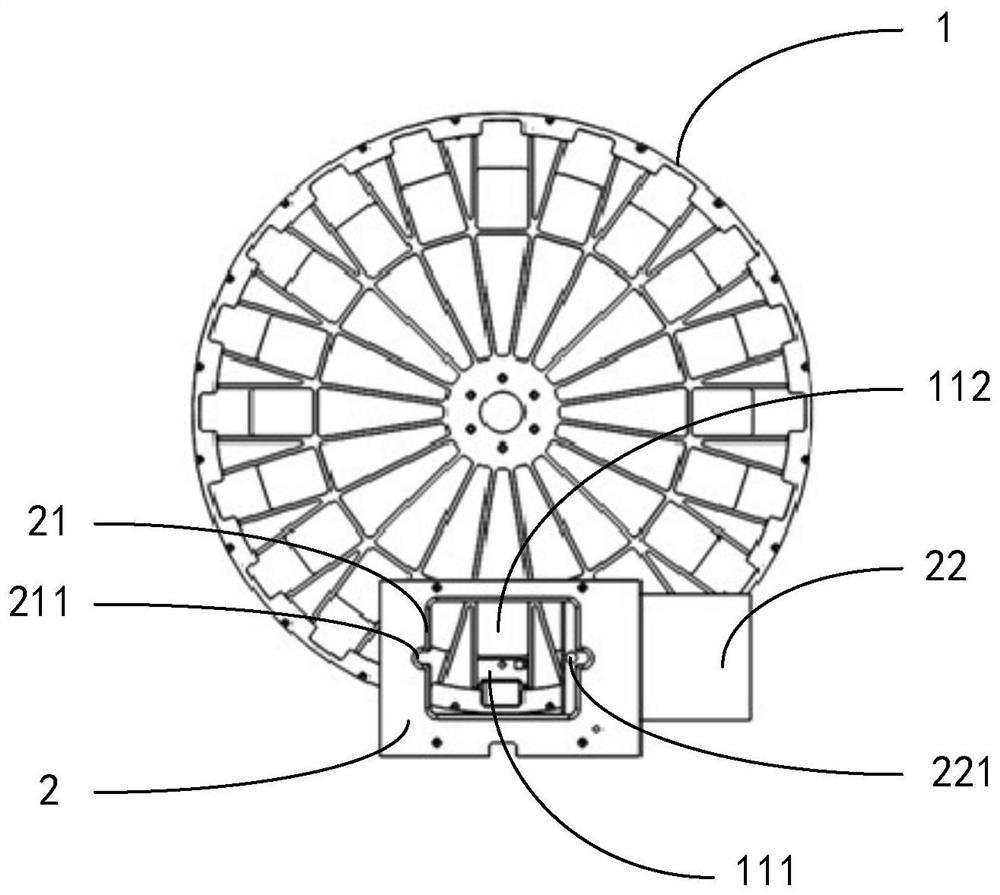
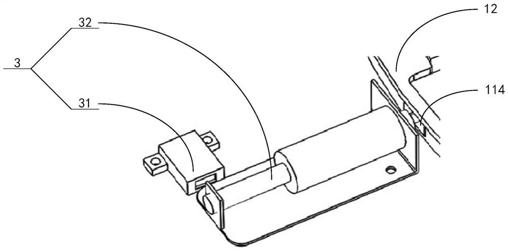
[0030] The embodiment of the present invention provides a rotor of a centrifuge. By designing a fixed stopper on the outside of the clamping position on the centrifugal turntable of the centrifuge, and setting an empty slot on the inside of the clamping position on the centrifugal turntable of the centrifuge, it is realized from the clamping position Insert the reagent card into the card position from the inside to the outside in the empty slot on the inner side and press against the stopper outside the card position. During centrifugation, the reagent card is blocked by the stopper outside the card position. At the same time, a controllable automatic The card ejection module can use the push-pull rod of the card ejection module to pop the reagent card in the card position into the empty slot from the card ejection port...


PUM


Abstract

The invention relates to a rotor of a centrifugal machine. The rotor comprises a centrifugal turntable, a card feeding module and a card discharging module, wherein the centrifugal turntable comprisesa chassis and a saw-shaped ring; a plurality card positions are uniformly distributed on a circle of the chassis; a hollow groove is formed in the inner side of each card position; a separation bladeis arranged on the outer side of each card position; card discharging openings are formed in parts, aligned with the middles of the card positions, of the separation blades; card discharging separation blades are arranged on the inner sides of the hollow grooves; the saw-shaped ring is fixed on the periphery of the chassis through a screw; the card feeding module is arranged above the card positions, and is provided with a first opening and a sliding door; the sliding door is used for opening or closing the first opening; and the card discharging module is positioned on the outer sides of thecard discharging openings, comprises an electromagnet and a push-pull rod, and is used for ejecting out reagent cards on the card positions from the card discharging openings. According to the embodiment of the invention, the feeding and discharging way of the reagent cards is improved through the improved centrifugal turntable, so that the phenomena that the reagent cards on the card positions fly off in centrifuging, and in card discharging, the reagent cards are stuck, resulting in damage of the centrifugal turntable are prevented.

Description

technical field [0001] The invention relates to the technical field of centrifugal detection, in particular to a rotor of a centrifuge. Background technique [0002] With the rapid development of biological engineering technology in the world, the detection and identification methods of cross-match blood, blood type and antibody have gradually changed from traditional blood type serological detection to micro-column gel immunoassay technology. The microcolumn gel immunoassay method must be equipped with a microcolumn reagent card. When testing, add blood to the reagent card, put the reagent card on the centrifugal turntable of the centrifuge, and fully combine the reagent with the blood through centrifugation to obtain the result. At present, when installing the reagent card on the centrifugal turntable of the centrifuge, the reagent card is usually pushed in from the outside of the centrifugal turntable and fixed by the buckle. When the buckle is not fastened or loose, th...

Claims


Application Information

Patent Timeline
IPC IPC(8): B04B7/00B04B5/12
CPCB04B7/00B04B5/12
Inventor 岳晓宇王丽黄志刚王伟权王秀柱
Owner TIANJIN DEXIANG BIOTECHNOLOGY CO LTD
Why Eureka
Try Eureka