
Outer speed governor for movable door plate

A technology of movable door panel and speed limiter, which is applied to switches with brake parts, door/window accessories, wing parts, etc. The effect of wide adjustment range and improved safety

Inactive Publication Date: 2021-02-12
丁井池
View PDF0 Cites 0 Cited by
  • Summary
  • Abstract
  • Description
  • Claims
  • Application Information

AI Technical Summary

Problems solved by technology

[0003] The purpose of the present invention is to provide an external speed limiter for a movable door panel to solve the problem that the existing door body fixer cannot prevent the violent collision between the movable door panel and the door frame

Method used


Image

  • Outer speed governor for movable door plate
  • Outer speed governor for movable door plate
  • Outer speed governor for movable door plate

Examples


Embodiment 1

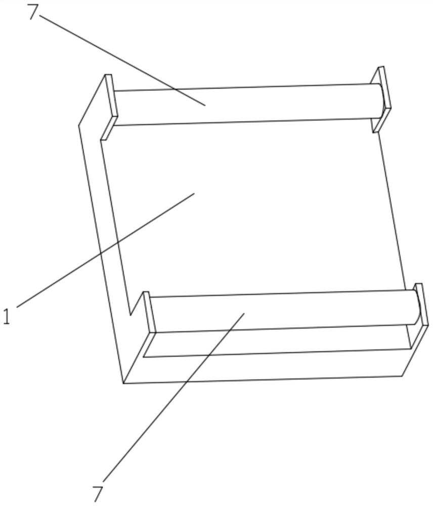
[0028] The speed limiter outside the movable door panel, the speed limiter includes a base 1, a sliding table 2, a roller 3, a spring 4 and an arc plate 5;

[0029] see figure 1 , the base 1 is fixedly installed on the edge of the movable door panel 6, the main body of the base 1 is a rectangular block, and a sliding rod 7 is arranged symmetrically above the rectangular block, and the sliding rod 7 matches the through hole 8 on the sliding table 2, Realize the purpose of sliding table 2 on the sliding bar 7;

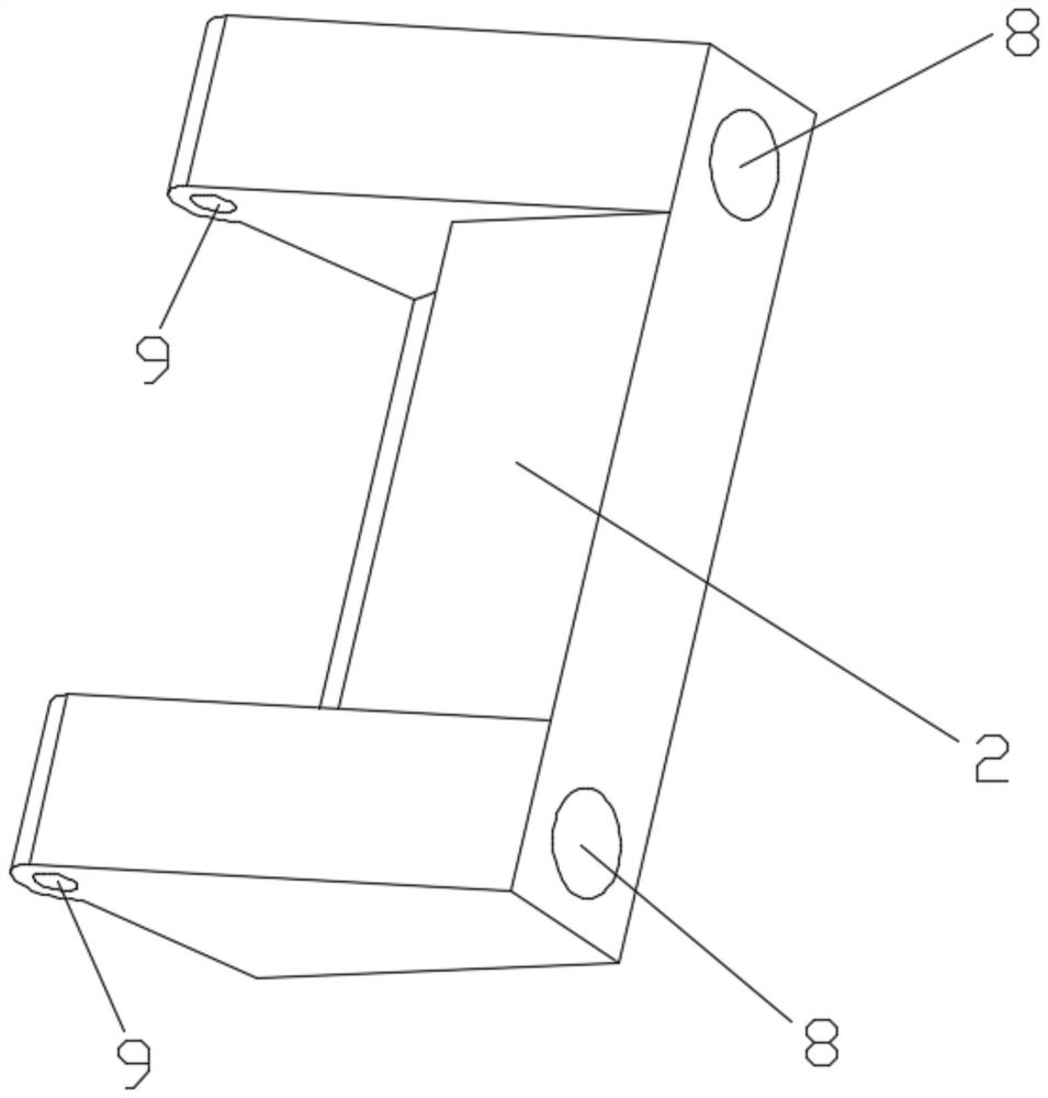
[0030] see figure 2 , the main body of the sliding table 2 is a rectangular block, the side of the rectangular block is symmetrically provided with through holes 8, the through holes 8 match the sliding rods 7 on the base 1, and one end of the upper surface of the rectangular block is provided with a roller installation hole 9, and the rollers 3 can be is constrained to rotate in the roller mounting hole 9;

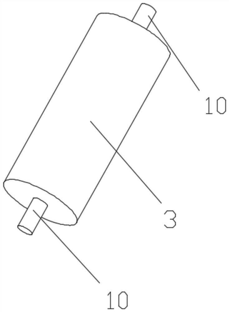
[0031] see image 3 , the main body of the roller 3 is a ...


PUM


Abstract

The invention discloses an outer speed governor for a movable door plate. The outer speed governor for the movable door plate comprises a base, a sliding table, a roller, springs and an arc-shaped plate, wherein a main body of the sliding table is a rectangular block; through holes are symmetrically formed in the side surfaces of the rectangular block; the through holes are matched with slide rodsarranged on the base; roller installing holes are formed in one end of the upper surface of the rectangular block, and the roller can be restrained to rotate in the roller installing holes; a main body of the roller is a cylinder; rotating shafts are arranged at two ends of the cylinder, and are matched with the roller installing holes formed in the sliding table; the arc-shaped plate is fixedlyarranged on a door frame; the contour of the arc-shaped plate is an arc line using a rotating shaft of the movable door plate as the circle center, and arc-surface projected blocks are arranged at theside, near the movable door plate, of the arc-shaped plate; after assembly, the roller can roll along the inner side of the arc-shaped plate along with rotation of the movable door plate; and when the roller encounters the projected blocks, the roller compresses the sliding table and moves back and forth under the action of the springs on the sliding table. The outer speed governor for the movable door plate solves the problem that violent collision between the movable door plate and the door frame cannot be prevented by an existing door body fixer.

Description

technical field [0001] The invention relates to a door panel movement speed limiter, in particular to an external speed limiter for a movable door panel. Background technique [0002] At present, with the improvement of living standards, people's requirements for the quality of life are increasing day by day, and they begin to pay attention to the details of life. In daily life, it is found that in places with abundant wind resources, the door is often opened suddenly or Closing, making a sudden sound or even hurting people, most of the restrictions on the door are currently adding a magnetic retainer behind the door panel to keep the door open. Once the magnetic retainer is separated, the door will be restored. In the out-of-control state, it cannot restrain the door panel activities, and cannot prevent the collision between the movable door panel and the door frame. Contents of the invention [0003] The purpose of the present invention is to provide an external speed l...

Claims


Application Information

Patent Timeline
IPC IPC(8): E05F5/02
CPCE05F5/02E05Y2900/132
Inventor 丁井池
Owner 丁井池
Learn More