
Gas inlet pipe structure of V-shaped engine

An air intake pipe and engine technology, which is applied to engine components, machines/engines, fuel air intakes, etc., can solve the problems of poor combustion, air grabbing, and high exhaust temperature, and achieves the goal of improving combustion efficiency, simple structure, and improved performance. Effect

Pending Publication Date: 2021-02-12
GUANGXI YUCHAI MASCH CO LTD
View PDF0 Cites 0 Cited by
  • Summary
  • Abstract
  • Description
  • Claims
  • Application Information

AI Technical Summary

Problems solved by technology

[0002] Due to the special structure of the V-type engine, there are cylinders on the left and right sides, and intake pipes need to be arranged on both sides. At this time, the gas after supercharging and intercooling needs to be reasonably distributed to the cylinders on the left and right sides to ensure the stable operation of the engine. , otherwise the air intake volume on one side is large and the air intake volume on the other side is small, which will lead to uneven work on both sides, and the side with small air intake volume will have problems such as poor combustion and high exhaust temperature. However, due to the existence of the V-shaped span and the engine itself Due to structural limitations, the direction, length, and diameter of the intake pipes leading to both sides cannot be designed to be exactly the same. In addition, the characteristics of the left and right sides of the V-type machine alternately intake air and work, and it is easy to "snatch air" on the left and right sides. phenomenon, for this purpose, we propose a V-shaped engine intake pipe structure

Method used


Image

  • Gas inlet pipe structure of V-shaped engine
  • Gas inlet pipe structure of V-shaped engine
  • Gas inlet pipe structure of V-shaped engine

Examples


Embodiment Construction

[0021] The present invention will be described in further detail below in conjunction with the accompanying drawings.

[0022] Wherein the same components are denoted by the same reference numerals. It should be noted that the words "front", "rear", "left", "right", "upper" and "lower" used in the following description refer to the directions in the drawings, and the words "bottom" and "top "Face", "inner" and "outer" refer to directions toward or away from, respectively, the geometric center of a particular component.

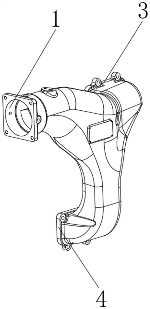
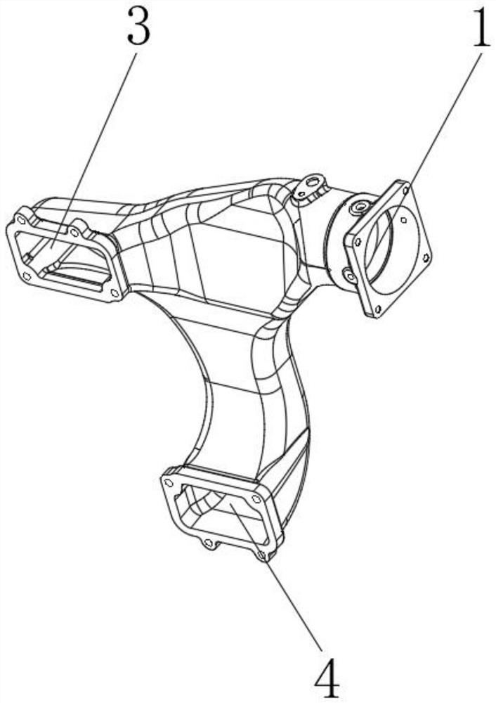
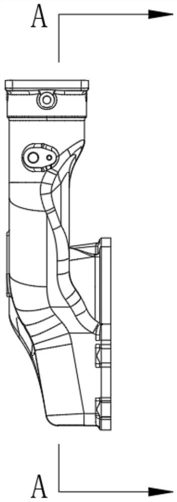
[0023] refer to Figure 1-5 As shown, a V-shaped engine intake pipe structure includes: an intake pipe, the outside of which is provided with an inlet pipe 1 connected to the intercooler, a left intake pipe 3 connected to the left cylinder of the engine, and a left intake pipe 3 connected to the left cylinder of the engine. The right air intake pipe 4, and the inlet pipe 1, the left air intake pipe 3 and the right air intake pipe 4 are all integrated with th...


PUM


Abstract

The invention discloses a gas inlet pipe structure of a V-shaped engine. The gas inlet pipe structure comprises a gas inlet connecting pipe and a pressure stabilizing cavity. An inlet pipeline connected with an intercooler, a left gas inlet pipe connected with a left gas cylinder of the engine and a right gas inlet pipe connected with a left gas cylinder of the engine are arranged outside the gasinlet connecting pipe, and the inlet pipeline, the left gas inlet pipe and the right gas inlet pipe are all of an integrated structure with the gas inlet connecting pipe. The pressure stabilizing cavity is formed in the inlet pipeline, and the inlet pipeline, the left gas inlet pipe and the right gas inlet pipe communicate with the pressure stabilizing cavity. According to the gas inlet pipe structure of the V-shaped engine, through structural optimization design to the gas inlet pipe, gas inlet pressure and gas inlet flow of the gas cylinders on the left side and the right side of the V-shaped engine are consistent, uniform gas input of all the gas cylinders is guaranteed, the combustion efficiency of the engine is effectively improved, and therefore the performance of the engine is improved, and the gas inlet pipe structure is simple in structure and easy to implement.

Description

technical field [0001] The invention relates to the field of internal combustion engines, in particular to a V-shaped engine intake pipe structure. Background technique [0002] Due to the special structure of the V-type engine, there are cylinders on the left and right sides, and intake pipes need to be arranged on both sides. At this time, the gas after supercharging and intercooling needs to be reasonably distributed to the cylinders on the left and right sides to ensure the stable operation of the engine. , otherwise the air intake volume on one side is large and the air intake volume on the other side is small, which will lead to uneven work on both sides, and the side with small air intake volume will have problems such as poor combustion and high exhaust temperature. However, due to the existence of the V-shaped span and the engine itself Due to structural limitations, the direction, length, and diameter of the intake pipes leading to both sides cannot be designed to ...

Claims


Application Information

Patent Timeline
IPC IPC(8): F02M35/116F02M35/10
CPCF02M35/10111F02M35/116
Inventor 余锦海廖升友刘治春覃文张文
Owner GUANGXI YUCHAI MASCH CO LTD
Learn More