Intelligent urban solar street lamp

A solar street light, intelligent technology, applied in the direction of energy-saving lighting, circuit layout, with built-in power supply, etc., can solve the problems of wasting energy, the brightness of street lights cannot be adjusted, and lighting cannot be achieved, so as to achieve better use effect

Active Publication Date: 2021-02-19
BEIJING TELECOM PLANNING & DESIGNING INST +1
View PDF6 Cites 4 Cited by
  • Summary
  • Abstract
  • Description
  • Claims
  • Application Information

AI Technical Summary

Problems solved by technology

[0003] At present, the existing street lamps still have certain shortcomings. During use, since the distance between the street lamps is fixed, when the height of the street lamps is low, it cannot meet the requirements of overlap at the edge of the illumination, resulting in the failure of some road sections to be illuminated. problem, and other light sources around some roads can also provide lighting for the road, but the brightness of street lights cannot be adjusted according to the surrounding environment, which is a waste of energy, and most street lights are fixed by bolts, and the bolts are easy to loosen after long-term use, which is very unsafe , therefore, there is an urgent need to design a smart city solar street light to solve the above problems

Method used


Image

  • Intelligent urban solar street lamp
  • Intelligent urban solar street lamp
  • Intelligent urban solar street lamp

Examples


Embodiment 1

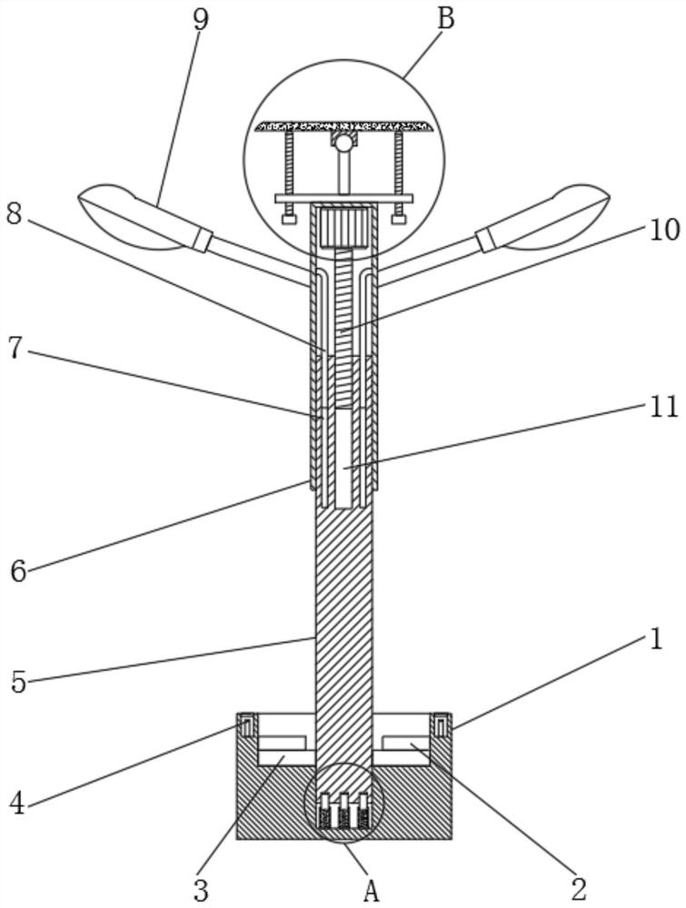
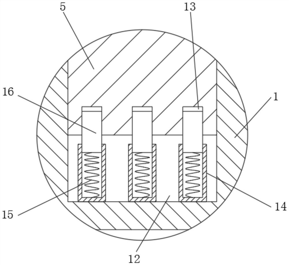
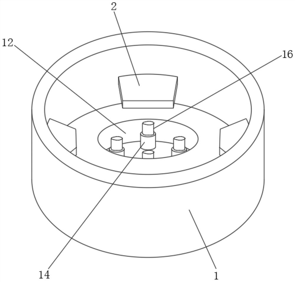
[0029] refer to Figure 1-4 , a smart urban solar street light, comprising a base 1 and a lamppost 5, the bottom inner wall of the base 1 has a slot 12, and the lamppost 5 is plugged into the slot 12, and the outer wall of the lamppost 5 is socketed with Lamp tube 6, and the outer walls of both sides of the lamp tube 6 are fixedly connected with lighting lamps 9, the top inner wall of the lamp tube 6 is provided with a stepper motor 17, and one end of the output shaft of the stepper motor 17 is provided with a screw rod 10, the lamp post The top of 5 is provided with a thread groove 11, and the outer wall of the screw rod 10 is threadedly connected with the inner wall of the thread groove 11, the top outer wall of the lamp tube 6 is provided with a photovoltaic mechanism, and the base 1 is provided with a fixing mechanism.

[0030] The inner wall around the lamp tube 6 is fixedly connected with the limit rod 8, the top outer wall of the lamp post 5 has a limit groove 7, and th...

Embodiment 2

[0038] refer to Figure 5 , a smart city solar street lamp, compared with Embodiment 1, this embodiment also includes side rods 25 fixedly connected to the outer walls around the base 1 , and steel wire mesh 26 is arranged between adjacent side rods 25 .

[0039] Working principle: when in use, when the base 1 is placed in the foundation pit for cement pouring, the side bars 25 and steel wire mesh 26 on the base 1 can increase the gripping force on the cement, making the base 1 more stable, It works better.


PUM


Abstract

The invention discloses an intelligent urban solar street lamp. The intelligent urban solar street lamp comprises a base and a lamp post. A slot is formed in the inner wall of the bottom of the base,and the lamp post is inserted into the slot. The outer wall of the lamp post is sleeved with a lamp barrel, illuminating lamps are fixedly connected to the outer walls of the two sides of the lamp barrel. A stepping motor is arranged on the inner wall of the top of the lamp barrel, and a lead screw is arranged at one end of an output shaft of the stepping motor. A threaded groove is formed in thetop end of the lamp post, and the outer wall of the lead screw is in threaded connection with the inner wall of the threaded groove. A photovoltaic mechanism is arranged on the outer wall of the top of the lamp barrel, a fixing mechanism is arranged in the base, and limiting rods are fixedly connected to the inner walls of the periphery of the lamp barrel. The illumination intensity of the illuminating lamps can be intelligently adjusted according to the surrounding environment, the energy-saving and environment-friendly requirements are met, the using effect is better, the illuminating lampscannot be detached from the outside, the street lamp has a certain anti-theft effect, a traditional bolt fixing mode is replaced, and the whole street lamp is more stable.

Description

technical field [0001] The invention relates to the technical field of street lamps, in particular to a smart city solar street lamp. Background technique [0002] Street lamps refer to lamps that provide lighting functions for roads, and generally refer to lamps within the range of road lighting in traffic lighting. Street lamps are widely used in various places that need lighting, and have become one of the indispensable auxiliary equipment in traffic roads. [0003] At present, the existing street lamps still have certain shortcomings. During use, since the distance between the street lamps is fixed, when the height of the street lamps is low, it cannot meet the requirements of overlap at the edge of the illumination, resulting in the failure of some road sections to be illuminated. problem, and other light sources around some roads can also provide lighting for the road, but the brightness of street lights cannot be adjusted according to the surrounding environment, whic...

Claims


Application Information

Patent Timeline
Patent Type & Authority Applications(China)
IPC IPC(8): F21S9/03F21V17/12F21V17/16F21V21/30F21V21/36F21V23/04F21V27/00H02S20/30F21W131/103
CPCF21S9/035F21V17/12F21V23/0464F21V17/164F21V21/30F21V27/00F21V21/36H02S20/30F21W2131/103Y02E10/50
Inventor 王珏胡雅静韩霄杨华新袁文国毕盛楠甘玲
Owner BEIJING TELECOM PLANNING & DESIGNING INST
Why Eureka
Try Eureka