Hall sensor of direct-current permanent magnet brushless motor

A permanent magnet brushless motor and hall sensor technology, applied in the direction of electrical components, electromechanical devices, etc., can solve the problems of larger structural size, difficulty in structural installation, and increased cost, so as to achieve small and convenient structure, generate commercial benefits, reduce cost effect

Inactive Publication Date: 2021-02-19
SUMEC HARDWARE & TOOLS
View PDF4 Cites 0 Cited by
  • Summary
  • Abstract
  • Description
  • Claims
  • Application Information

AI Technical Summary

Problems solved by technology

[0002] With the increasing demand for products powered by DC batteries in the market, the demand for DC permanent magnet brushless motors has also begun to increase, and DC permanent magnet brushless motors have also begun to be widely used in various electrical appliances; the DC permanent magnet brushless motors currently on the market Magnetic brushless motors often use Hall position sensors to determine the rotor position relationship. In a three-phase six-state DC permanent magnet brushless motor, the conventional design uses three Hall sensors placed on a circumferential PCB board at intervals of 120° , the Hall PCB is arranged around the rotor magnetic steel, and the structural size becomes larger with the increase of the diameter of the motor. Structural installation difficulties and increased costs

Method used


Image

  • Hall sensor of direct-current permanent magnet brushless motor
  • Hall sensor of direct-current permanent magnet brushless motor

Examples


Embodiment Construction

[0015] The following examples are only used to illustrate the technical solution of the present invention more clearly, but not to limit the protection scope of the present invention.

[0016] It should be noted that if there is a directional indication (such as up, down, left, right, front, back...) in the embodiment of the present invention, it is only used to explain the relationship between the components in a certain posture. If the specific posture changes, the directional indication will also change accordingly.

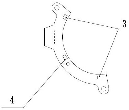
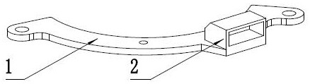
[0017] A Hall sensor for a DC permanent magnet brushless motor, comprising a PCB board, a Hall socket, several Hall sensor ones and several Hall sensor twos, the Hall socket is fixedly arranged on the PCB board, and the Hall sensor one and Hall sensor two are fixed on the PCB board. Hall sensor 2 is fixedly arranged on the PCB board, Hall sensor 2 is located between several Hall sensor 1, Hall sensor 2 is located in two Hall sensor 1 and arranged at intervals ...


PUM


Abstract

The invention discloses a Hall sensor of a direct-current permanent magnet brushless motor, which is characterized by comprising a PCB, a Hall socket, a plurality of Hall sensors I and a plurality ofHall sensors II, wherein the Hall socket is fixedly arranged on the PCB, the Hall sensors I and the Hall sensors II are fixedly arranged on the PCB, the second Hall sensors are located between the first Hall sensors, and the second Hall sensors are located between the two first Hall sensors and are arranged at intervals of 30-90 degrees. The Hall PCB of the direct-current permanent magnet brushless motor is small, simple and convenient in structure, the Hall PCB can be more conveniently installed on the direct-current permanent magnet brushless motor, a traditional large-size Hall PCB is replaced, the cost of the Hall PCB is reduced, and commercial benefits are generated.

Description

technical field [0001] The invention relates to a Hall sensor of a DC permanent magnet brushless motor, belonging to the technical field of Hall sensors. Background technique [0002] With the increasing demand for products powered by DC batteries in the market, the demand for DC permanent magnet brushless motors has also begun to increase, and DC permanent magnet brushless motors have also begun to be widely used in various electrical appliances; the DC permanent magnet brushless motors currently on the market Magnetic brushless motors often use Hall position sensors to determine the rotor position relationship. In a three-phase six-state DC permanent magnet brushless motor, the conventional design uses three Hall sensors placed on a circumferential PCB board at intervals of 120° , the Hall PCB is arranged around the rotor magnetic steel, and the structural size becomes larger with the increase of the diameter of the motor. Structural installation is difficult and costly. ...

Claims


Application Information

Patent Timeline
Patent Type & Authority Applications(China)
IPC IPC(8): H02K29/08
CPCH02K29/08H02K2211/03
Inventor 刘楷林有余陈伟汪洋周建辉
Owner SUMEC HARDWARE & TOOLS
Why Eureka
Try Eureka