Locking device

A locking device and a pair of technology, applied in the field of locking technology on storage boxes, can solve the problems of inconvenient disassembly, small contact area, and large force, and achieve easy manufacturing and disassembly, not easy to wear, and effective small force effect

Pending Publication Date: 2021-02-23
广州金大森汽车部件有限公司
View PDF3 Cites 0 Cited by
  • Summary
  • Abstract
  • Description
  • Claims
  • Application Information

AI Technical Summary

Problems solved by technology

[0002] As disclosed in the patent application CN2003101034736, the existing locking technology for the axially supported and rotatable storage box on the vehicle instrument panel is to provide swing power through the operating handle, so that the cam part is opposite to the cam groove 18 on the sliding pin. Move, drive the sliding pin to move left and right. In this structure, the cam part and the cam groove on the sliding pin are in line contact, the

Method used


Image

  • Locking device
  • Locking device
  • Locking device

Examples


Example Embodiment

[0015]The present invention will be further described in connection with the accompanying drawings and examples:

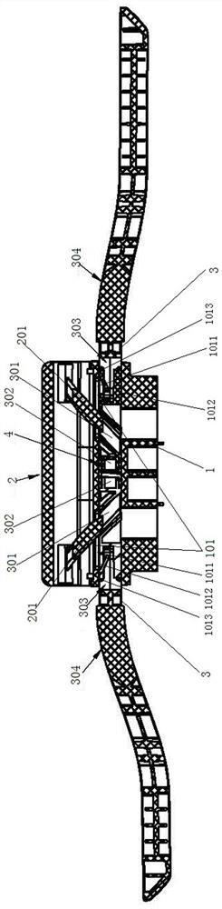
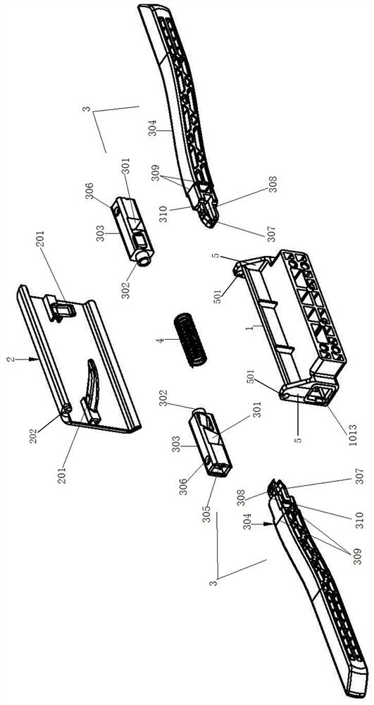
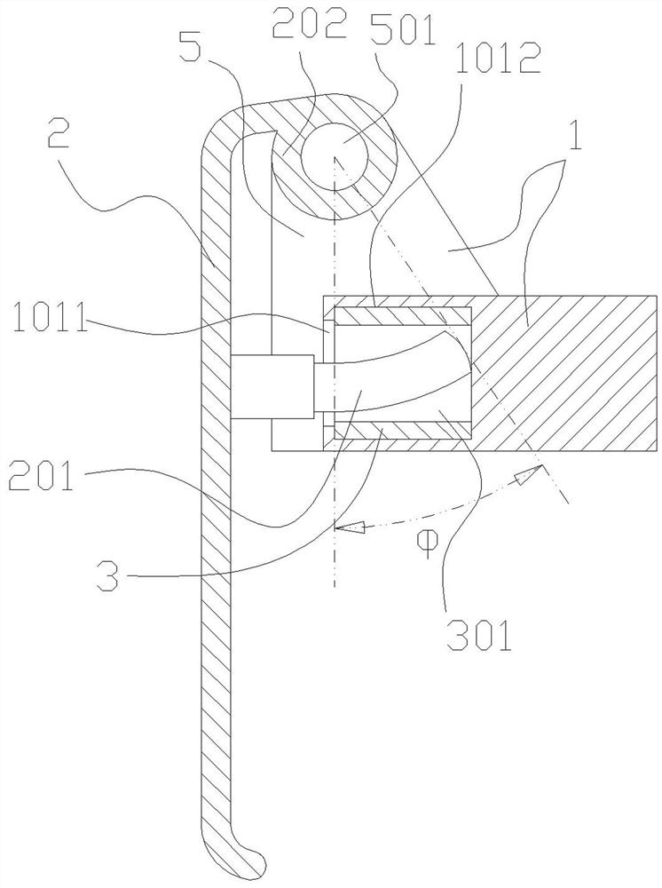
[0016]Such asfigure 1 As shown, the present invention includes a support frame 1, a handle 2 disposed on the support frame 1, a pair of slide pin 3, the spring ring 4, which is particularly provided in both sides of the support frame 1, and a guide structure 101, a pair The sliding pin 3 slides on the guiding structure 101 on both sides of the support frame 1, and a hole-like chute 301 is provided on the slide pin 3, and the chute 301 is obliquely towed toward the middle portion of the support frame 1, the corresponding slant groove 301. The handle 2 is provided with a curved drive rod 201, the free end of the drive rod 201 to the middle portion of the handle 2, and the spring ring 4 is disposed between a pair of sliding pins 3.

[0017]A handle joint 5 is provided on both sides of the support frame 1, and the shaft hole 202 on the upper edge of the handle 2 is rotated on the...


PUM


Abstract

A locking device comprises a supporting frame, a handle arranged on the supporting frame in a swinging mode, a pair of sliding pins and a spring ring, and is characterized in that guide structures arearranged on the two sides of the supporting frame respectively, the pair of sliding pins are arranged on the guide structures on the two sides of the supporting frame respectively in a sliding mode,and chutes are formed in the sliding pins. A bent driving rod is arranged on the handle corresponding to the inclined groove, a spring ring is arranged between the pair of sliding pins, handle connecting seats are arranged on the two sides of the supporting frame, and the handle is connected to the handle connecting seats in a rotating mode. Compared with the prior art, the device has the advantages of being high in reliability, simple in structure, low in manufacturing cost and easy to disassemble and assemble.

Description

technical field [0001] The invention relates to a locking technology, in particular to a locking technology used on a storage box which is axially supported and rotatable on the instrument panel of a vehicle. Background technique [0002] As disclosed in the patent application CN2003101034736, the existing locking technology for the axially supported and rotatable storage box on the vehicle instrument panel is to provide swing power through the operating handle, so that the cam part is opposite to the cam groove 18 on the sliding pin. Move, drive the sliding pin to move left and right. In this structure, the cam part and the cam groove on the sliding pin are in line contact, the contact area is small, the force is large, and the shape of the cam groove is easily changed due to wear and tear, resulting in the failure of the sliding pin. Normal telescoping affects its reliability in use, and since the sliding pin needs to be guided to prevent it from rotating, the operating ha...

Claims


Application Information

Patent Timeline
IPC IPC(8): B60R7/06
CPCB60R7/06Y02T10/70
Inventor 陶涛盘庆学
Owner 广州金大森汽车部件有限公司
Why Eureka
Try Eureka