Automatic driving truck head and trailer included angle measuring and calculating device and method

A technology of automatic driving and computing devices, which is applied to vehicle components, transportation and packaging, and can solve problems such as the difficulty in measuring the angle between the tractor head and the trailer

Active Publication Date: 2021-02-23
北京主线科技有限公司
View PDF10 Cites 6 Cited by
  • Summary
  • Abstract
  • Description
  • Claims
  • Application Information

AI Technical Summary

Problems solved by technology

[0005] The main purpose of the present invention is to provide a device and method for measuring and calculating the angle between the front of the tru

Method used


Image

  • Automatic driving truck head and trailer included angle measuring and calculating device and method
  • Automatic driving truck head and trailer included angle measuring and calculating device and method
  • Automatic driving truck head and trailer included angle measuring and calculating device and method

Examples


Embodiment 1

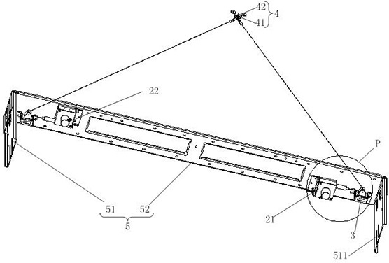
[0049]Such asfigure 1 ,Figure 4 withFigure 5 As shown, the embodiment of the present invention is presented by an automatic driving truck head and a trailer angle measurement computing device, including:

[0050]Both of which are pulled first displacement sensors 21 and the second displacement sensor 22, the controller, the first displacement sensor 21, and the second displacement sensor 22, are connected to the controller;

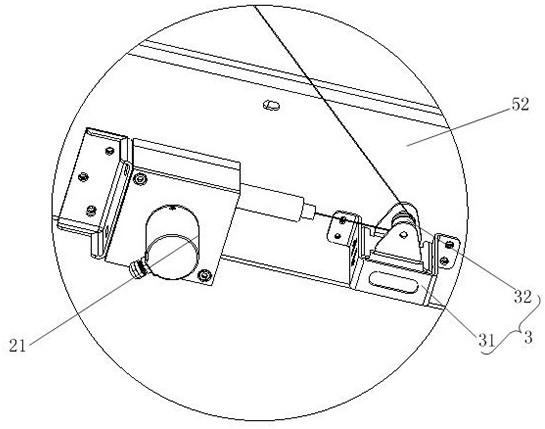
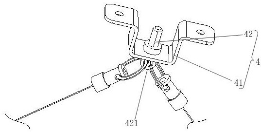
[0051]The first displacement sensor 21 and the second displacement sensor 22 are respectively coupled at the bottom of the trailer 2, located at a position near the trailer 2, and the first displacement sensor 21 and the second displacement sensor 22 are respectively located. On both sides of the midwork of the trailer 2; the pull end portion of the first displacement sensor 21 is simultaneously coupled to the mounting point 23 of the traction saddle 11 of the traction head 1 at the end portion of the second displacement sensor 22;

[0052]Wherein the controller can obt...

Embodiment 2

[0072]The second embodiment of the present invention proposes a method for measuring and calculating the angle between the front of an autonomous truck and the trailer. The method is used in a device for measuring and calculating the angle between the front of an autonomous truck and the trailer, including:

[0073]201. Obtain the first distance data between the first displacement sensor and the second displacement sensor, and at the same time obtain the second distance between the installation point of the first displacement sensor and the second displacement sensor and the traction saddle and the traction pin data.

[0074]Specifically, the device for measuring and calculating the angle between the front of the autonomous truck and the trailer is as described in the first embodiment, and will not be repeated here. After the device for measuring and calculating the angle between the front of the self-driving truck and the trailer is installed on the self-driving truck, the first distance...


PUM


Abstract

The invention provides an automatic driving truck head and trailer included angle measuring and calculating device and method, and relates to the technical field of automatic driving. The measuring and calculating device comprises a first displacement sensor, a second displacement sensor and a controller, the first displacement sensor and the second displacement sensor both arestay wire type, areconnected to the bottom of a trailer, located close to the front end of the trailer and located on the two sides of the center line of the trailer in the width direction. The stay wire end part of thefirst displacement sensor and the stay wire end part of the second displacement sensor are simultaneously connected to a mounting point of a traction saddle of a traction headstock; and the controller can obtain first distance data between the first displacement sensor and the second displacement sensor, obtain second distance data between the mounting point and the traction pin, and obtain current stay wire absolute length data of the first displacement sensor and the second displacement sensor. And a preset function is used for calculating the current included angle between the traction headstock and the trailer.

Description

Technical field[0001]The present application relates to the field of automatic driving technology, in particular to a automatic driving truck head and a trailer angle measurement computing device and method.Background technique[0002]In recent years, with the development of automatic driving technology, there is already a considerable part of the automatic driving truck to operate in the port, high speed and other scenes.[0003]However, unlike civil cars with compact vehicles, trucks are divided into two parts of traction head and trailers, both through the traction pin of the head, relatively moved in both portions of the body when turning or reversing, causing the two sports The direction is inconsistent, producing a certain angle. In order to ensure that the automatic driving truck can steadily reverse the track, and meet some of the possible functional needs of future other modules, it is necessary to get the direction of the trailer relative to the front of the head, and ensure i...

Claims


Application Information

Patent Timeline
IPC IPC(8): B60W30/18B60W40/00B60W60/00B60R11/00
CPCB60R11/00B60W30/18145B60W40/00B60W60/00
Inventor 张沐豪张维辰左建坡王晓东张天雷
Owner 北京主线科技有限公司
Why Eureka
Try Eureka