
A special ladder for replacing tension bar insulators

A technology of insulators and tension rods, which is applied to ladders, buildings, building structures, etc. It can solve the problems of replacing insulators without using force, long replacement time, complicated operation, etc., so as to reduce the risk of potential safety hazards and facilitate maintenance Effect

Active Publication Date: 2022-05-06
GUIZHOU POWER GRID CO LTD
View PDF0 Cites 0 Cited by
  • Summary
  • Abstract
  • Description
  • Claims
  • Application Information

AI Technical Summary

Problems solved by technology

[0002] To replace the 35-110kV tension rod insulators during a power outage, the maintenance personnel need to stand upside down on the insulators with their feet up and their heads down. The time is too long, and the operator has a great safety risk during the work of overhauling the insulator

Method used


Image

  • A special ladder for replacing tension bar insulators
  • A special ladder for replacing tension bar insulators
  • A special ladder for replacing tension bar insulators

Examples


Embodiment 1

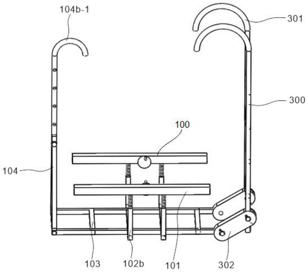
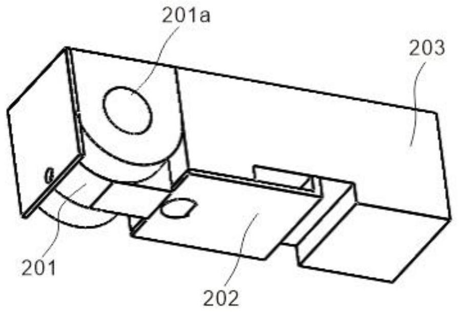
[0037] refer to Figure 1~4 , which is the first embodiment of the present invention, this embodiment provides a special ladder for replacing tension bar insulators, the special ladder for replacing tension bar insulators includes a first ladder body 100, a telescopic unit 200 and a second ladder body 300 , the first ladder body 100 and the second ladder body 300 can be switched between the straight ladder and the working platform through the connecting piece 302, and the telescopic unit 200 can make the hollow cross bar 101 switch between the guardrail and the handrail.

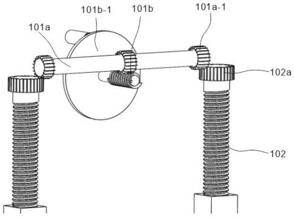
[0038] Specifically, the first ladder body 100, the hollow cross bar 101 and several first studs 102, the hollow cross bar 101 is provided with a cylinder 101a and a second stud 101b inside, and the middle and two ends of the cylinder 101a are respectively A first gear 101a-1 is provided, and the first gear 101a-1 in the middle part of the cylinder 101a cooperates with the second stud 101b, and one end of th...

Embodiment 2

[0043] refer to Figure 5-13 , is the second embodiment of the present invention, which is different from the first embodiment in that: in the last embodiment, the special ladder for replacing the tension bar insulator includes a first ladder body 100, a telescopic unit 200 and a second ladder Body 300, the first ladder body 100 and the second ladder body 300 can be switched between the straight ladder and the working platform through the connecting piece 302, and the telescopic unit 200 can make the hollow cross bar 101 switch between the guardrail and the handrail.

[0044] Specifically, the first ladder body 100, the hollow cross bar 101 and several first studs 102, the hollow cross bar 101 is provided with a cylinder 101a and a second stud 101b inside, and the middle and two ends of the cylinder 101a are respectively A first gear 101a-1 is provided, and the first gear 101a-1 in the middle part of the cylinder 101a cooperates with the second stud 101b, and one end of the se...


PUM


Abstract

The invention discloses a new type of special ladder for replacing tension bar insulators, which includes a first ladder body, a telescopic unit and a second ladder body. The first ladder body includes a hollow cross bar, a first stud, a first pedal, a V-shaped A column, a second rotating shaft and a slot, the telescopic unit includes a rotating structure, a buckle, and a second square column, and the second ladder body includes a first arc-shaped hook, a connecting piece, a rotating buckle and a second pedal. The device of the invention ensures the safety of the maintenance personnel during work, and at the same time brings convenience to the maintenance personnel. By switching between two different forms of the ladder, the maintenance personnel can perform maintenance more conveniently and reduce the risk of potential safety hazards. .

Description

technical field [0001] The invention relates to a ladder, in particular to a special ladder for replacing tension bar insulators. Background technique [0002] To replace the 35-110kV tension rod insulators during a power outage, the maintenance personnel need to stand upside down on the insulators with their feet up and their heads down. If the time is too long, the operator has a great safety risk during the work of overhauling the insulator. Therefore, a safe and convenient special ladder is needed. Contents of the invention [0003] The purpose of this section is to outline some aspects of embodiments of the invention and briefly describe some preferred embodiments. Some simplifications or omissions may be made in this section, as well as in the abstract and titles of this application, to avoid obscuring the purpose of this section, the abstract and titles, and such simplifications or omissions should not be used to limit the scope of the invention. [0004] In view...

Claims


Application Information

Patent Timeline
Patent Type & Authority Patents(China)
IPC IPC(8): E06C1/36E06C1/38E06C7/18E06C7/50
CPCE06C1/36E06C1/38E06C7/50E06C7/181
Inventor 陈强
Owner GUIZHOU POWER GRID CO LTD
Learn More